
Dronetag BS
- Document
- Dronetag BS
- Chapters
- 19
- Source
- help.dronetag.cz/print/dronetag-bs
Dronetag BS
Please note that orders placed after mid-January 2024 will be supplied with Dronetag BS gen.2.
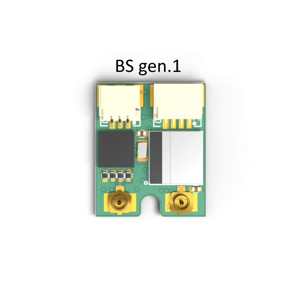
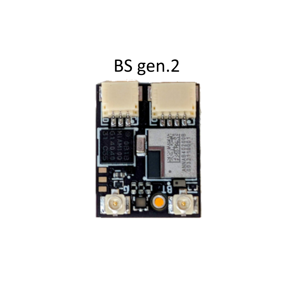
To identify which BS generation you possess, simply refer to the color.
Generation 1 features a green PCB color, whereas Generation 2 showcases a black color.
This color difference will help you determine the version you have. Below you can find an illustrative example and links to support pages for a specific generation of BS.
|
|
The Dronetag BS enriches the Dronetag Remote ID device family with an affordable, lightweight and cost-effective solution for all aeromodelers, FPV pilots, and hobbyists. With its affordable price point and lightweight design, the Dronetag BS is a perfect fit for those seeking to comply with FAA (US) and EASA (EU) Remote ID regulations. It is compatible with Remote ID rules in other territories that accept ASTM F3411 or EN 4709-002 standards.
The ready-to-install design of the Dronetag BS ensures a hassle-free setup process. It can be powered using an up to 17V power input or, if preferred, an external LiPo battery can be utilized as an alternative.
Weighing in at only 0.105 oz (1.5 grams) with basic wire antennas and measuring 0.66 x 0.55 x 0.19 in (17 x 14 x 5 mm) in size, the Dronetag BS is suitable even for the smallest aircraft that are required to have Remote ID capabilities. Mounting the BS model is effortless and can be done using double-sided tape or velcro, offering flexibility across multiple aircraft.
Utilizing Bluetooth technology for Remote ID, the Dronetag BS can transmit signals within a range of up to 1.86 miles (3 kilometers) in ideal conditions.
You can manage the BS with ease through our Dronetag App for Android and iOS. No more hassle of disassembling your aircraft just to adjust settings or update the firmware. With our convenient multiplatform mobile app, you can care for everything effortlessly.
- Before using Dronetag BS, we highly advise reviewing the Power Source Installation page.
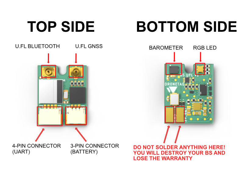
- Do not solder anything to your BS! The two soldering pads located on the bottom side of the BS device are exclusively designed for internal purposes within Dronetag. It is crucial to emphasize that any attempt to use or solder anything onto these pads will result in irreversible damage to your BS device and will consequently void your warranty.
- Using powerful batteries to power BS can potentially cause damage. Please read the Notice for products bought before 10/16/2023.
Who is it for?
Dronetag BS is mainly for skilled recreational pilots (RC modelers, FPV pilots, hobbyists) seeking the simplest and most flexible Remote ID solution on the market to comply with the latest regulations. It is unsuitable for people looking for a plug & play solution as it requires at least some basic electronic expertise to have it up and running. The customers need to find an appropriate power source on their aircraft and do the setup + wiring themselves. If you are looking for off-the-shelf solutions, please get Dronetag Beacon or Mini.
Customers using off-the-shelf drones such as DJI are most likely unable to use BS due to the lack of open interfaces/power outputs available on such aircraft.
Difference between Dronetag BS and Dronetag DRI
The main difference between BS and DRI is the ability to work as a standalone system. Dronetag BS has everything needed to get you Remote ID compliant, which includes an internal GNSS receiver. On the other hand, Dronetag DRI is mainly an OEM product for integrators and manufacturers that relies on sensor information being provided by the flight controller. If you need a self-contained & standalone system, go with Dronetag BS. If you need Standard Remote ID implementation, it is suggested to go with Dronetag DRI.
What's in the Box
Dronetag BS comes as a barebone device. In the packaging you will find:
- 1 × Dronetag BS
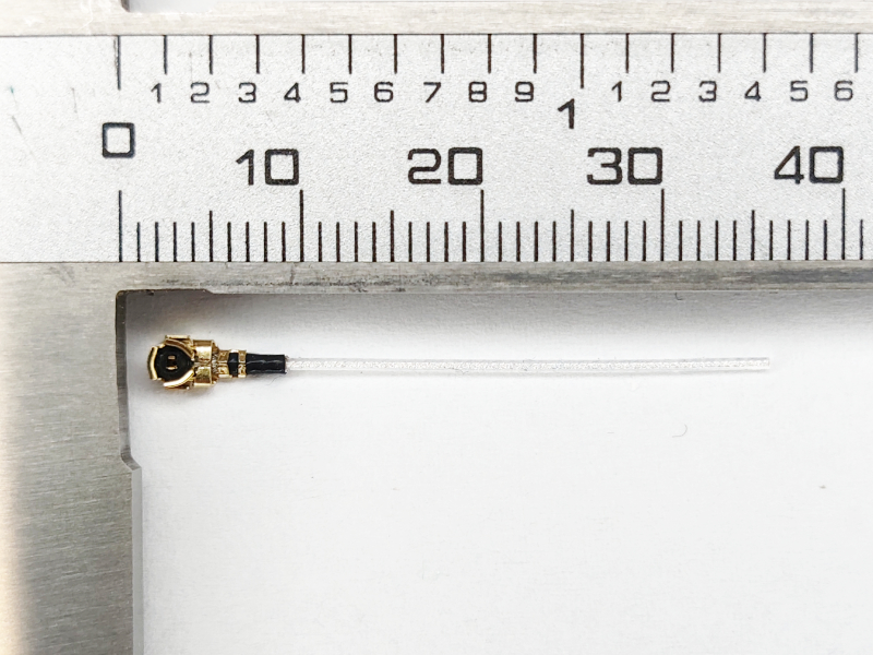
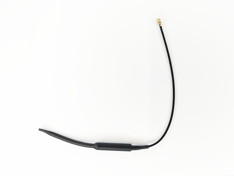
- 1 × Bluetooth 2.4 GHz wire antenna (the shorter one with black cable isolation)
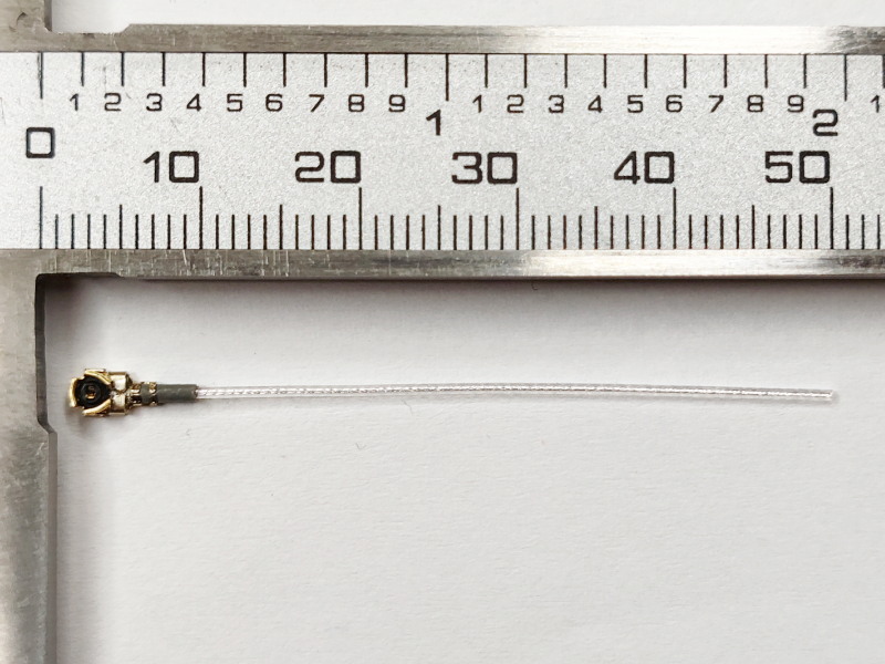
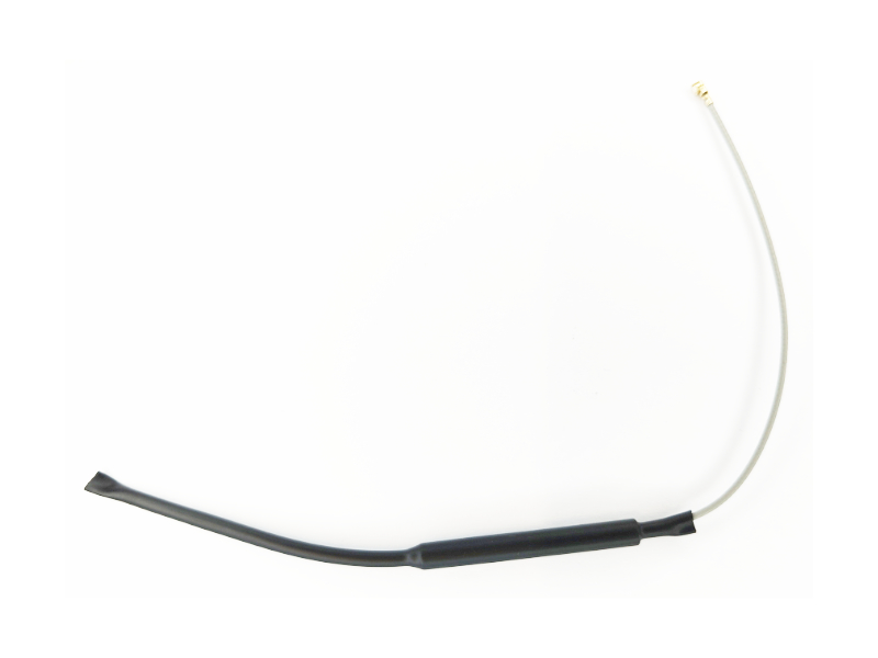
- 1 × GNSS 1.575 GHz wire antenna (the longer one with grey cable isolation)
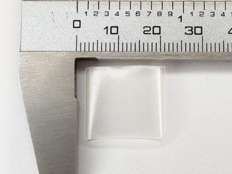
- 1 × Transparent heat shrink tube
Other equipment such as batteries, more advanced antennas, or an enclosure is not included.
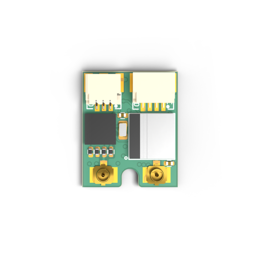
What is included visualized
Dronetag BS
 |
Heat-shrink Tube
 |
GNSS Wire Antennas (Grey Isolation)
 |
Bluetooth Wire Antennas (Black Isolation)
 |
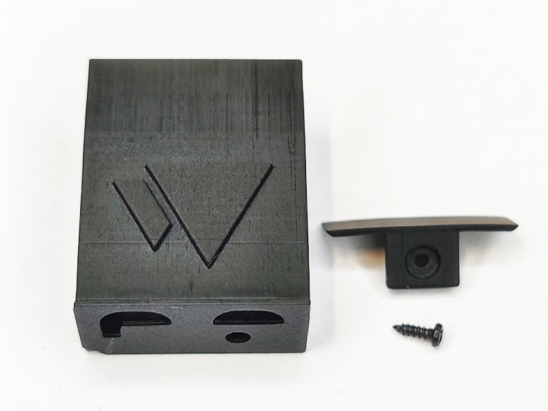
Optional items (Available on our eshop)
 |
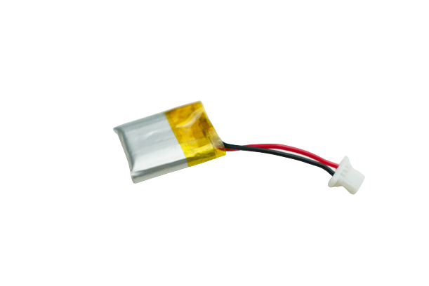 |
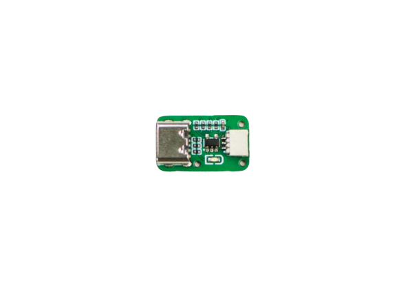
The battery charger is not supposed to be permanently attached to the Dronetag BS and should be used only for battery charging in a safe environment.
 |
 |
 |
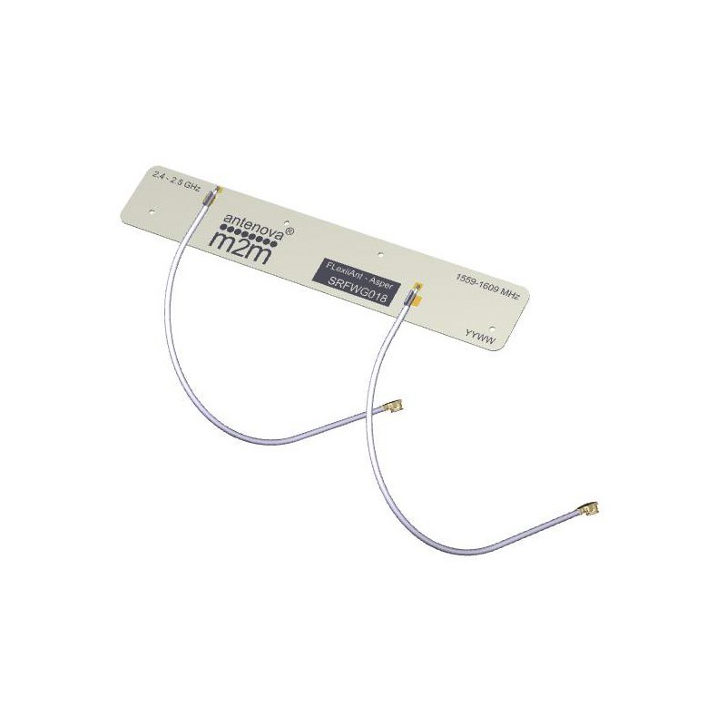
Combined Bluetooth & GNSS antenna
 |
Optional items (Available on 3rd party eshops)
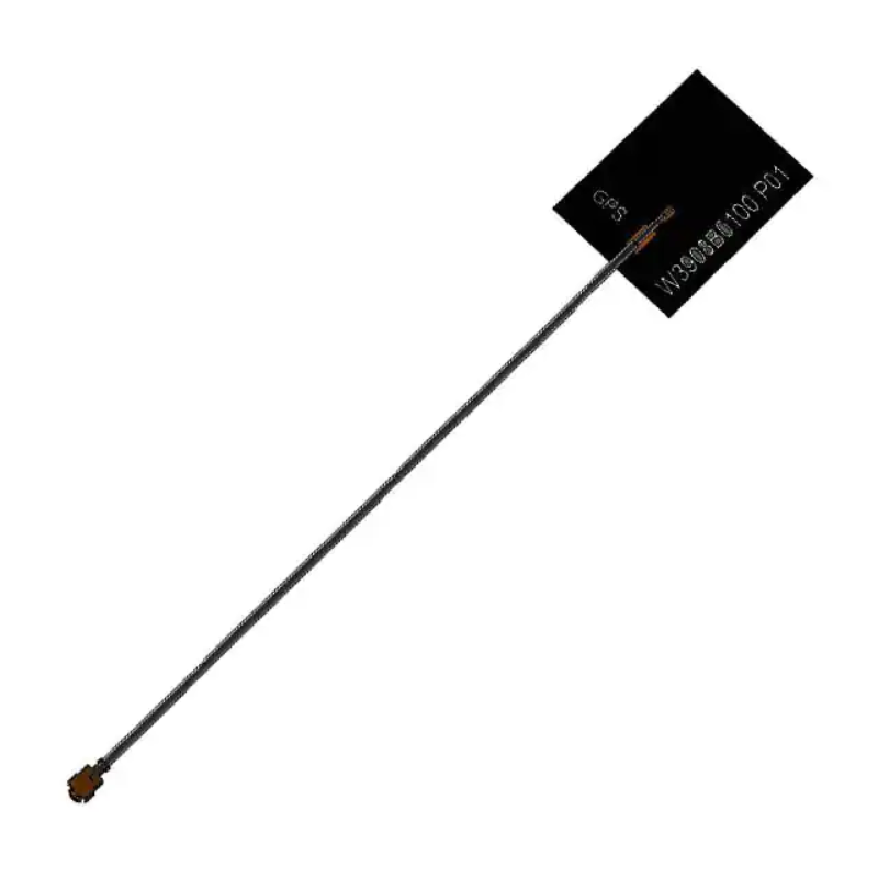
GNSS antenna
 |
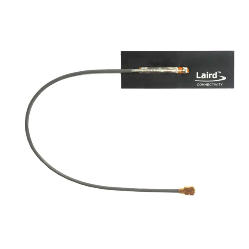
High Performance Bluetooth antenna
 |
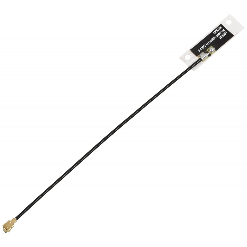
Compact Bluetooth antenna
 |
Safety Notices
Dronetag BS has been created for the most straightforward handling possible. Still, the following safety notes must be followed to reduce the risk of accidents, injuries and device malfunction to a minimum. If misused, it has the potential for causing fire or personal injury. Dronetag is not liable for damages arising from the use or misuse of this product. To help ensure accident-free operation, follow these guidelines:
- This and the Dronetag App manual must be read carefully, and all instructions must be followed. Special attention must be taken to all warnings and precautions.
- The user is solely responsible for the risk while using this device. Dronetag is not responsible for any injuries or accidents that are a result of improper use.
- The input voltage is from 3.3V to a maximum of 17V. We highly advise reviewing the Power Source Installation page.
- Do not allow liquid, small particles or other foreign objects to get into the system or accessories.
- Do not expose the system or accessories to high temperatures, high humidity or direct sunlight.
- Keep the system and accessories, including cable ties and fasteners, out of the reach of small children.
- If the system is brought directly from a cold location to a warm one, moisture may condense inside the system. If this occurs, the system may not operate properly. In this case, unplug all cables/accessories immediately and leave the device in a dry place for several hours.
- Stop using the system and disconnect it from any connectors immediately if the device functions abnormally, produces unusual sounds or smells, or becomes too hot to touch.
Serial Number
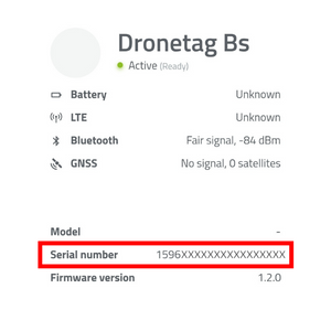
To get the SN from your Dronetag BS, you need to use our Dronetag App or the Toolbox App. After plugging the BS into the power source and its registration in the app, you can manually write down the serial number of your Dronetag BS.
 |
Specification
Dronetag BS transmits position and identification data adhering to Direct (Broadcast) Remote ID regulations. Its transmission follows the standards outlined in prEN 4709-002 for the EU and ASTM F3411 for the US. Dronetag BS is officially recognized as a Remote ID solution on the EASA website and has been approved by the FAA as one of the initial Remote ID modules. You can verify the Declaration of Compliance here.
| Parameter | Value |
|---|---|
| Remote ID types | Direct (EU) / Broadcast (US) |
| Remote ID technology | Bluetooth 4.0 Legacy + 5.0 Long Range |
| Short-range radio | Bluetooth 2.4GHz |
| Bluetooth output power | 8 dBm |
| Average current consumption | 15 mA |
| Maximum current consumption | 50 mA |
| Mounting mechanism | Adhesive or velcro |
| Operating temperature | -40°C to +85°C (-40°F to 185°F) |
| Dimensions | 17 x 14 x 5 mm (0.66 x 0.55 x 0.19 in) |
| Weight /w heat shrink + wire antennas | 1.5 grams (0.05 oz) |
| Weight /w enclosure + wire antennas | 3 grams (0.1 oz) |
| Supported baud rates | Standard ones - configurable in Dronetag app |
| Input voltage | 3.3 – 17V |
| Input voltage regulator | Low-noise buck converter |
| Remote ID Standards | ASD-STAN EN 4709-002 & ASTM F3411-22 |
| Certifications | Uses FCC/CE approved radio module |
| Indicators | RGB LED to show the state |
High-level List of Features
Flexible Antenna Selection
Dronetag BS comes with two standard U.FL connectors for external GNSS positioning and Bluetooth broadcasting antennas. This gives customers the freedom to select the specific antenna shape, size, cable length and performance. The only requirement we put on the antenna selection is that they must be U.FL compatible and the Bluetooth antenna must be tuned for 2.4 GHz and the GNSS antenna for 1.575 GHz.
Flexible Power Input Source
Dronetag BS can be powered from any power input capable of supplying 3.3V to 17V. It uses a buck regulator to convert the power input to an internal voltage level. The power source must withstand 50 mA peak currents at 3.3V. The most common place to get power input is the regulated voltage on the flight controller, or you can use an aircraft battery (up to 4S Li-Po). For some scenarios, you can also use a small external single-cell LiPo battery to power the device.
GNSS Input to Betaflight
If you use a Betaflight controller, you can use Dronetag BS as a GNSS input for telemetry information and the GPS rescue feature. The device uses the ublox M10 chipset, which provides state-of-the-art positioning for your aircraft.
GNSS Timekeeping with Supercapacitor
Waiting for a GNSS fix can be a lengthy process. And it isn't very pleasant when you already had the fix, but you power-cycled your aircraft, and you have to wait for the GNSS fix again. For this reason, we added a tiny supercapacitor to the board, which can hold up the GNSS data in RAM for around 8 minutes. This means that whenever you have a position fix and you do a power cycle of the BS, you won't have to wait again to acquire a fix as the data will be stored inside the RAM. This feature dramatically reduces the time to first fix (TTFF) so you can experience continuous flying during the battery change process.
Operating as Telemetry Modules for Futaba, Spektrum, etc.
This feature is currently in development and a firmware update will be released in the near future.
Flight Data Logging into Internal Flash Memory
This feature is currently in development and a firmware update will be released in the near future.
Integration of Dronetag BS
Betaflight
Dronetag BS can feed GPS data to the Betaflight flight control software through the XBUS protocol, acting as a GPS module. Connecting Dronetag BS to the Spektrum telemetry receiver will enable you to access live positioning data.
Betaflight Software configuration
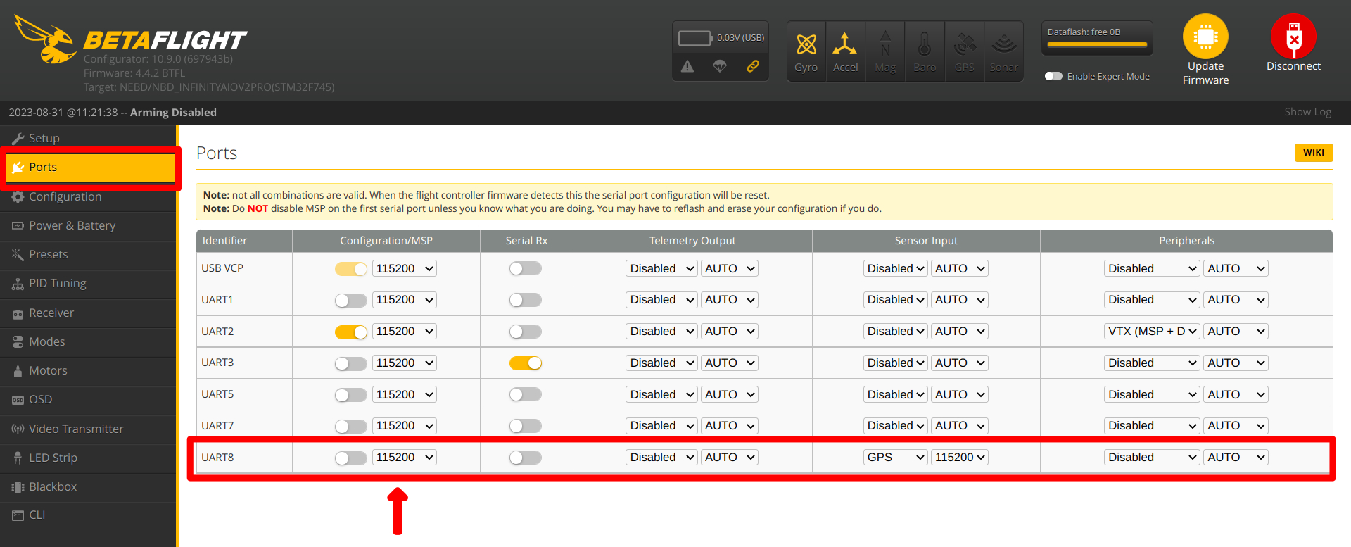
Ports
UART X - set the Sensor Input GPS to value: 115200
 |
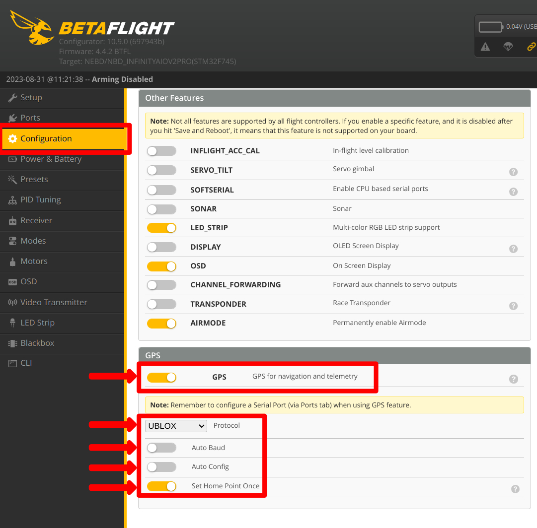
Configuration
GPS: Enabled Protocol: UBLOX Auto Baud: Disabled Auto Config: Disabled
 |
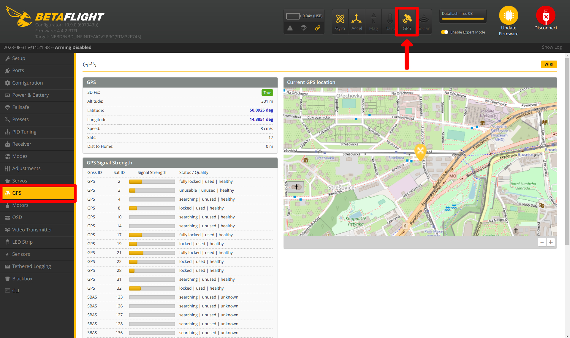
Confirmation of functionality
Confirm the GPS connection in the top right. The icon should be yellow.
 |
Advanced
In Expert mode, look at the number of satellites. If you are having trouble getting a fix with the BS, please restart the Module and upload Assisted GNSS data.
 |
Betaflight Flight Controller integration
Connect the flight controller with free UART port of the Flight controller.
Example:
Follow the wiring diagram for BS 4-pin Connector below. Be extra careful to avoid connecting VCC and GND to the module them reversing will permanently damage the module.
4-pin Connector (Placed on Left Side)
The connector placed on the left side of the Dronetag BS is a common JST SH 4-pin with UART interface with no flow control. This connector will also be used for support for Betaflight communication and Spektrum Telemetry XBUS in the future.
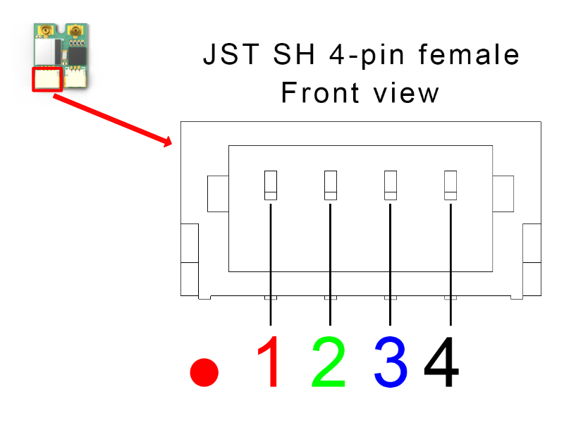
| Pin # | Name | Scheme Color | Description |
|---|---|---|---|
| 1 | VCC | Red | 3.3V to 17V. Directly connected to pin 1 at the 3-pin connector |
| 2 | UART RX | Green | Receive of the Dronetag device (3.3V logic - 5V tolerant) |
| 3 | UART TX | Blue | Transmit of the Dronetag device (3.3V logic - 5V tolerant) |
| 4 | Ground | Black | Ground connection |
VCC pin 1 is directly interconnected with VCC pin 1 at the 3-pin JST SH (the other connector)
Integration with Spektrum devices
New Feature Introduced in the Latest Firmware Update
The Dronetag BS now supports integration with Spektrum receivers. By connecting the Dronetag BS to an SRXL2-compatible or XBUS-compatible device, the BS supplies additional telemetry data that is seamlessly transmitted to your drone's transmitter. This allows you to view important telemetry information directly on your transmitter display during operation, enhancing your situational awareness and providing additional data you may require for safe and efficient drone flights.
SRXL2 Setup and Connection Manual
1. Setup
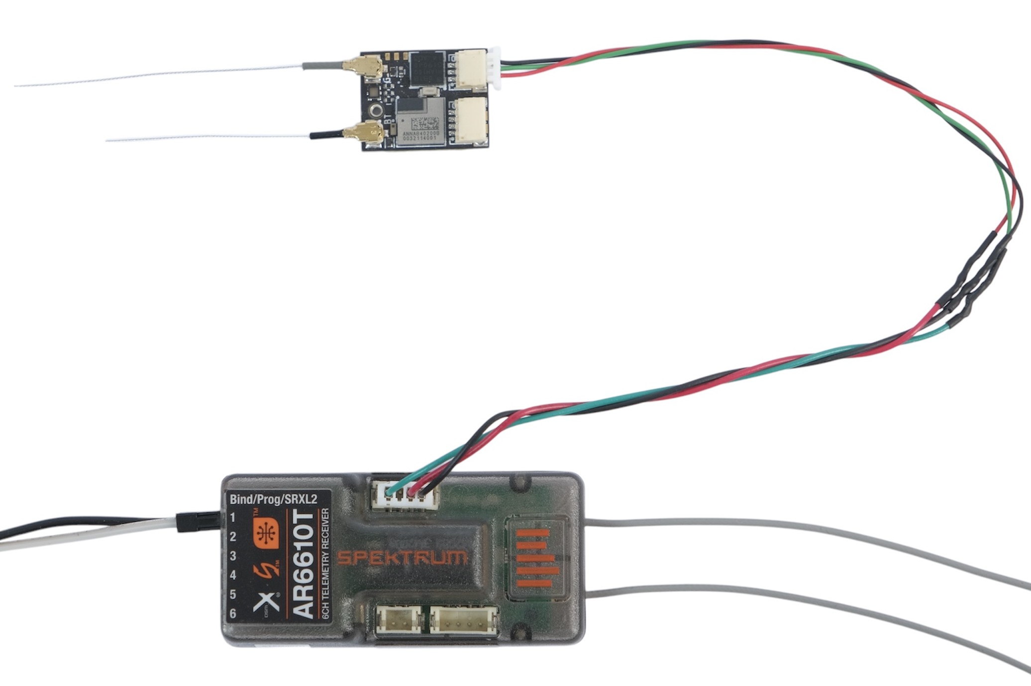
In this example, we’ll use the Spektrum receiver AR6610T, which provides SRXL2 as well as an XBUS interface.
2. Connection
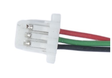
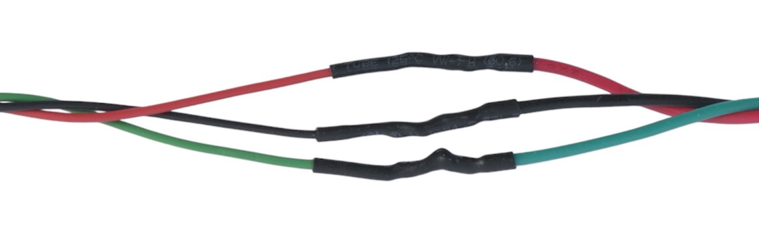
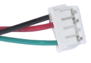
To connect the SRXL2-compatible device to the Dronetag BS, you’ll need to make a custom cable. On the Dronetag BS side, the cable requires a 3-pin connector (3-pin JST SH Series). On the Spektrum side, refer to the appropriate connector specified in the device datasheet (in our case, a 4-pin JST ZH connector with a 1.5 mm pitch - one pin is unused).
Keep in mind that the Dronetag BS still requires power. Ensure the power pins are connected, and verify that the Spektrum device can supply sufficient current. Refer to the image below for guidance:
For the pinout reference:
- BS side: Refer to the 3-pin connector description.
- Spektrum side: Refer to the device's datasheet.
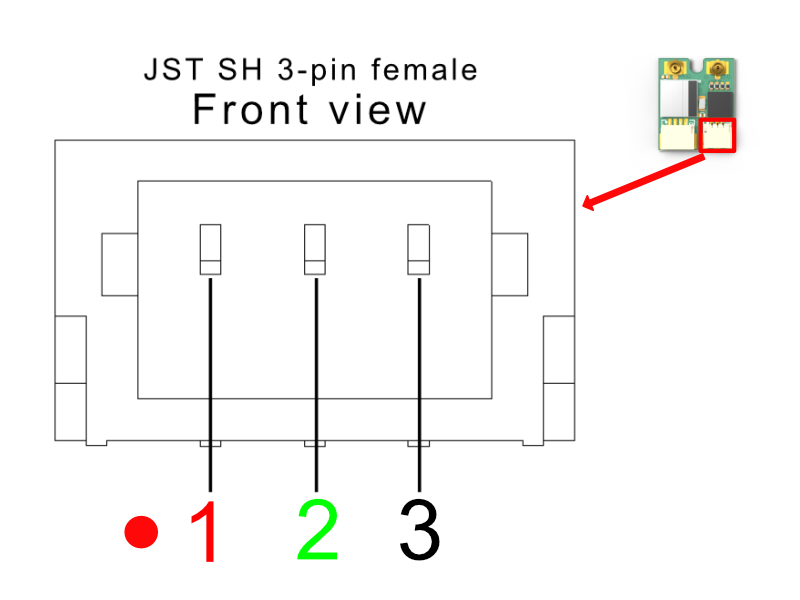
| Pin # | Name | Scheme Color | Description |
|---|---|---|---|
| 1 | VCC | Red | 3.3V to 17V. Directly connected to pin 1 at the 4-pin connector |
| 2 | RESERVED | Green | SRXL2 data pin |
| 3 | Ground | Black | Ground connection |
3. Power On and Operation
- No special power-up sequence is required.
- No additional settings need to be configured in the Dronetag mobile app.
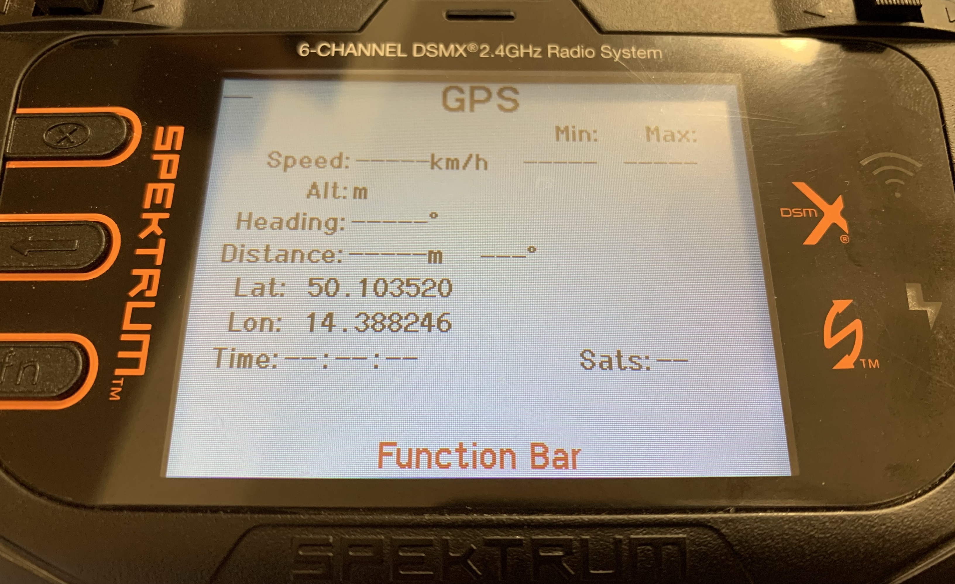
After powering on both devices, you should see the live telemetry data on the screen of the transmitter (in this example Spektrum NX6 DSMX) as soon as the Dronetag BS obtains a GPS fix.
XBUS Setup and Connection Manual
1. Setup
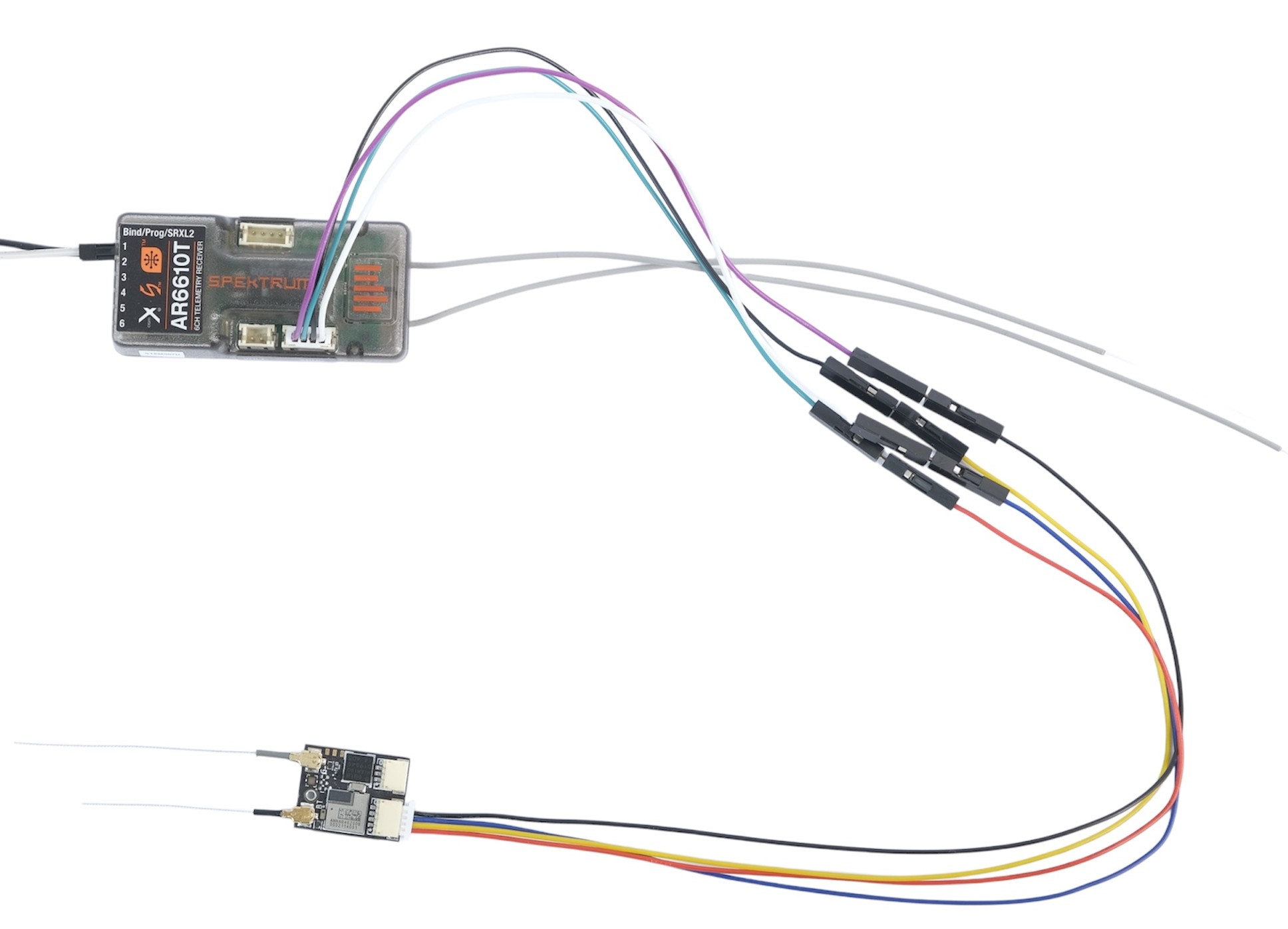
For this XBUS example, we’ll use the Spektrum receiver AR6610T.
2. Connection
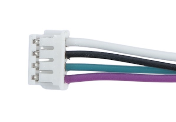
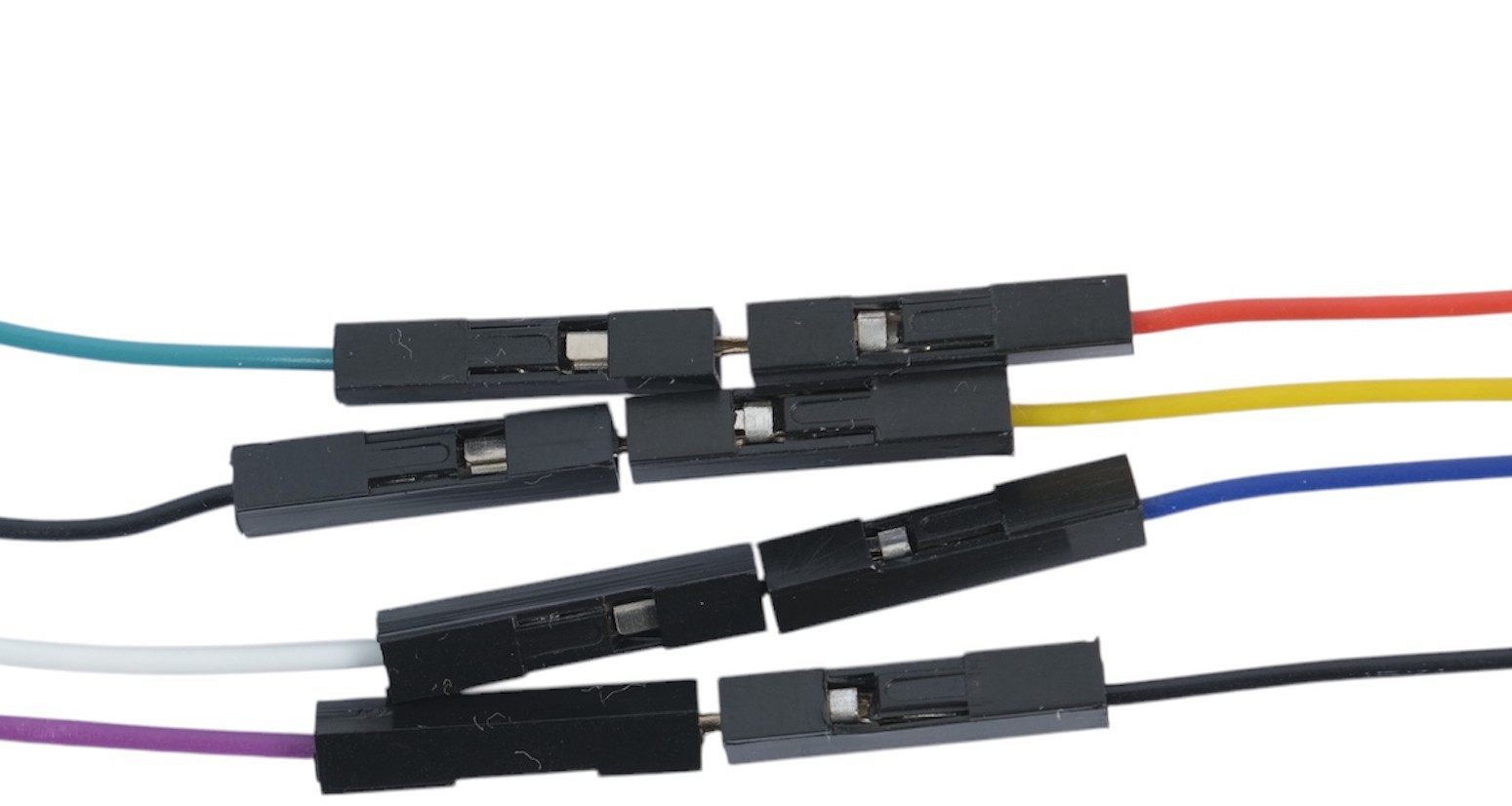
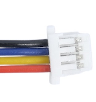
To connect an XBUS-compatible device to the Dronetag BS, you’ll need to create a custom cable, slightly different from the SRXL2 configuration. On the Dronetag BS side, the cable requires a 4-pin connector (4-pin JST SH Series). On the Spektrum side, refer to the appropriate connector specified in the device datasheet (in this case, a 4-pin JST ZH connector with a 1.5 mm pitch).
Keep in mind that the Dronetag BS still requires power. Ensure the power pins are connected, and confirm that the Spektrum device can supply sufficient current. Refer to the image below for guidance.
Pinout reference:
- BS side: Refer to the 4-pin connector description below.
- Spektrum side: Refer to the device's datasheet.
| Pin # | Name | Scheme Color | Description |
|---|---|---|---|
| 1 | VCC | Red | 3.3V to 17V. Directly connected to pin 1 at the 3-pin connector |
| 2 | XBUS I2C SCL | Green | I2C Serial Clock (3.3V logic - 5V tolerant) |
| 3 | XBUS I2C SDA | Blue | I2C Serial Data (3.3V logic - 5V tolerant) |
| 4 | Ground | Black | Ground connection |
3. Power On and Operation
There are specific steps required to establish communication with XBUS:
-
Configuration settings:
Open the Dronetag app, navigate to the "Configuration" section, and under "4 Pin Connector Selection," set the function to "Spektrum XBUS." -
Power-up sequence:
Both devices must be powered on simultaneously to ensure the initial XBUS handshake is established. If powered on separately, the handshake may fail, and communication will not work.
After a successful connection, you should see the telemetry information displayed on the screen of your transmitter.
Usage Options
Whether you have a drone that you built yourself, you fly an FPV drone, or you have any kind of aircraft, with Dronetag BS you can rest assured that you will find a solution that perfectly aligns with your unique needs.
The beauty of BS lies in its design and multi-scalability, which enables effortless customization. We understand that no two customers are the same, and that's why we have meticulously crafted BS with components, ready to meet any specific requirement.
Enclosure Options
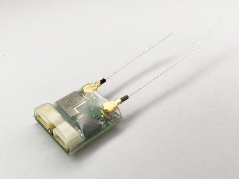
- Never use the device without either a heat shrink tube or an enclosure! Otherwise you damage your device and void the warranty. The exposed board is sensitive to accidental tearing off of electronic parts, which will prevent the device from normal operation. It is also prone to a short circuit, which might cause a fire on your aircraft.
Heat-Shrink Tube
When used with our basic wire antennas and external power source, the heat shrink tube option is the lightest option available (1.5 grams in total). Please check out this page on how to install the heat shrink tube.
Enclosure
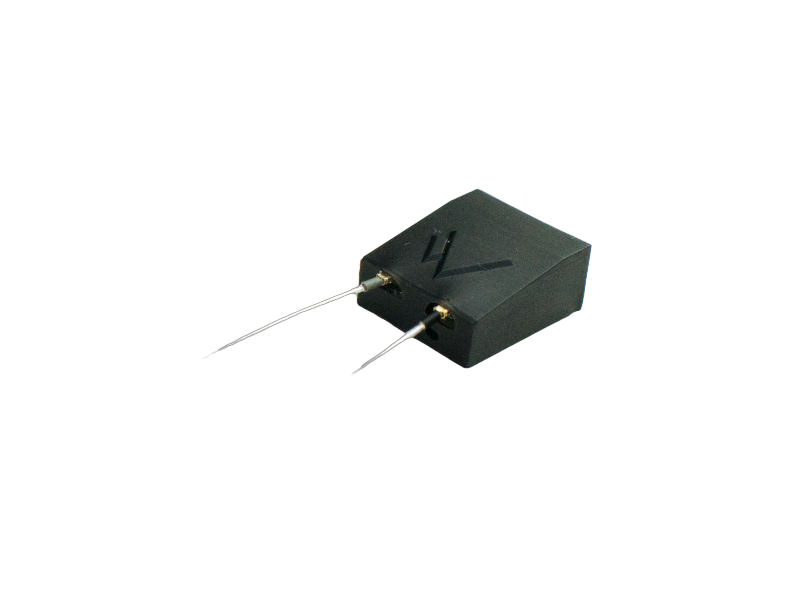
For extra protection and easier transferability between different aircraft models, we recommend purchasing the optional 3D printed enclosure. Compared to the heat shrink tube option, the weight increases by 1.5 grams (3 grams in total). Please check out this page on how to install the enclosure.
Power Input Options
-
Never use input voltage that falls outside the operating range of 3.3V to 17V or you damage your device and void the warranty.
-
Never supply both connectors with power input or you damage the device and connected power sources.
-
We highly advise reviewing the Power Source Installation page.
External Power Supply
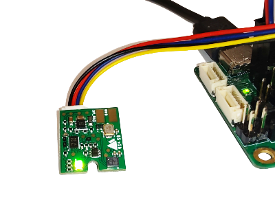
You can power Dronetag BS directly from your aircraft if you have suitable power output ports available. Please check the section Powering from Aircraft VIN for more details. Using the power from the aircraft eliminates the need to use an external battery.
External Battery
By incorporating an external battery, Dronetag BS becomes a completely standalone unit. However, you need to think of the battery placement as the current enclosure or heat shrink tube doesn't allow the battery to be fitted in. Therefore, your own enclosure, heat shrink tube or mounting needs to be established. You can get our small LiPo battery that can power up Dronetag BS for more than 4 hours.
Antenna Options:
Wire Antennas
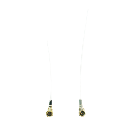
Wire antennas are part of the minimalistic approach of Dronetag BS product. They are very compact and lightweight (just 0.15 grams each). However, their performance might be very limiting in some scenarios (e.g. big electromagnetic interference due to high transmission power of other aircraft onboard equipment). Please ensure to upload assisted GNSS data before each flight (the upload can be done via our Dronetag app, check the short video here). This step is needed due to the limited power of the Wire antennas.
Copper Tube antennas
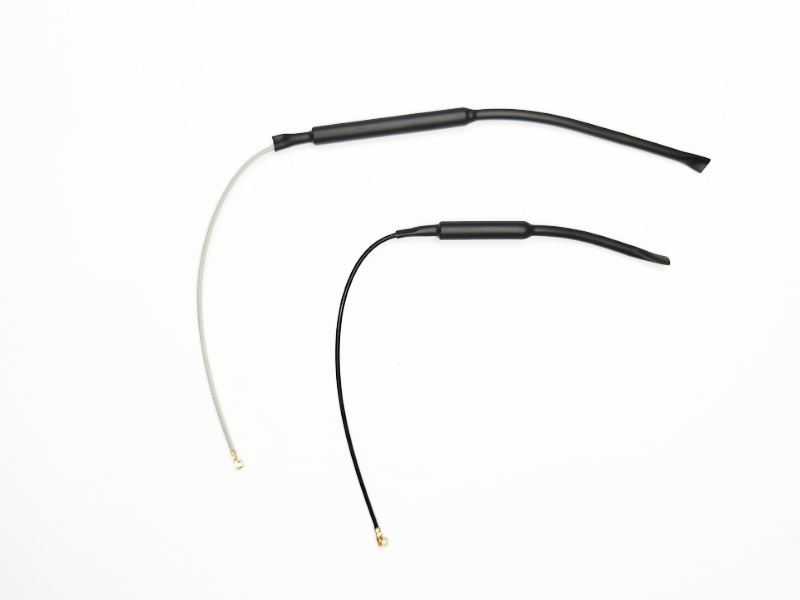
For better positioning and broadcasting performance, we recommend getting a pair of our copper tube antennas (GNSS and Bluetooth). They provide higher flexibility when you want to place Dronetag BS into the fuselage because then you can easily wire the antennas out of the aircraft.
Custom Antennas
If the two above options don't suit your needs, you can also use 3rd party options available on the market. However, you must ensure that the Bluetooth antenna for Remote ID is tuned for 2.4 GHz and the GNSS antenna for positioning is tuned for 1.575 GHz. One of the popular 3rd party options is combined Bluetooth and GNSS antenna that comes with an adhesive.
- Never use Dronetag BS without antennas or you damage your device and void the warranty. Always stick to the antenna options above. If you are unsure about the antenna selection, ask us for a recommendation / approval.
Heat-shrink Tube Installation
Items Required
- Dronetag BS unit
- Heat-shrink tube
- Selected antennas
- Heat gun
- It's important to use a heat gun designed for this purpose, as uncontrolled heat sources can result in uneven shrinkage, physical damage, and insulation failure.
- Only use a heatgun to shrink the tube around the BS unit. Avoid using an open flame as a substitute for a heat gun, as this can lead to damage and safety hazards.
- Follow these instructions carefully to ensure a successful heat shrink tube installation. Any deviations may result in improper insulation, damage to the equipment, or safety hazards. Always prioritize safety when using heat tools and ensure proper ventilation while operating the heat gun.
Procedure
1. U.FL Antenna Installation
U.FL connectors are commonly used for antenna connections in space constrained products such as our Dronetag DRI and Dronetag BS. Due to their size, they are not designed with regular reconnection in mind, and they are only rated for a few dozen mating cycles (usually just 30). It is therefore crucial to select the proper antenna and ideally connect it once for the lifetime of the product. However, U.FL connectors are suitable for scenarios where you need to do the antenna replacement (e.g. when it is no longer working properly or you upgrade to a better antenna).
Before you try to connect or disconnect the U.FL antennas on our products, we recommend studying the U.FL tips from SparkFun and reading the instructions below.
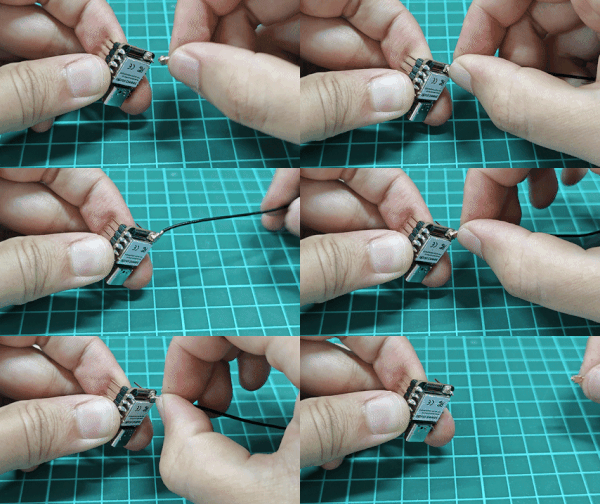
U.FL connector mating and unmating process (source Seeed Studio)
How to Connect U.FL
- Disconnect your device from any power supply and keep it turned off.
- Take the U.FL antenna and align it accurately over the U.FL female counterpart on the PCB board.
- Press down gently until you hear a satisfying click.
- Check whether you can rotate the antenna freely and if possible, protect the connector from external factors.
- If it takes too much force for the connection, you are probably misaligned.
How to Disconnect U.FL
Disconnecting the U.FL can be quite tricky as there is a possibility of damaging the PCB board counterpart or antenna. Be careful during the process. You shouldn't need any tool for the removal and we strongly discourage using a screwdriver or similar that might damage the PCB board.
- Hold the cable with your nails as close to the connector as possible (ideally try to hold the metal stiffener built into the connector)
- Gently rotate and tilt the cable from the connector all the way up until it pulls away.
- Inspect the connectors on both sides and examine them for possible damage.
- For the removal process, you shouldn't really need much force to do it.
You should hear a click when the antennas are securely attached.
- Ensure that you orient the antennas correctly, ensuring that the GNSS antenna and the Bluetooth antenna align with the appropriate connectors on the BS unit.
- If you are using wire antennas, the shorter one with black isolation is for Bluetooth Remote ID and the longer one with gray isolation is for GNSS positioning.
2. Insertion into Heat Shrink Tube Carefully slide the BS unit with the installed antennas into the heat-shrink tube. Position the BS unit in the center of the tube. Make sure the antennas protrude from one end of the tube, while the battery connectors are accessible from the other end. Heat-shrink tube must be positioned evenly around the BS unit.
3. Even Application of Heat Begin heating the tube by moving the heat gun back and forth along the length of the tube. This ensures even distribution of heat and prevents damage to the wire inside. Do not concentrate heat in one spot for too long, as this can cause overheating and wire damage.
5. Secure Attachment Continue applying heat until the heat shrink tube tightly conforms to the shape of the BS unit. The tube should be securely attached to the BS unit and covering the U.FL connectors.
6. Cooling Period Allow the assembly to cool down for a moment before handling it. This ensures that the tube is no longer extremely hot and can be safely touched.
7. Final Check Once the tube has cooled down, visually inspect the installation to ensure that the tube is securely attached, antennas are properly positioned, and battery connectors are accessible.
8. Usage After confirming the secure and proper installation of the heat shrink tube, the BS unit with antennas can be used as intended.
Where to Get Heat-shrink Tube Replacement?
If you for some reason need a new heat-shrink tube for Dronetag BS, please contact your local electronics/hobby store for replacement. You must ensure that the replacement is transparent with a length of 17mm, diameter before shrinkage approx. 12 mm, and diameter after shrinking: approx 7.5 mm.
Enclosure Installation
Items Required
- Dronetag BS unit
- Enclosure
- Selected antennas
- M1 3mm Philips head screw
- Philips head screwdriver
These instructions must be meticulously followed to ensure a successful BS installation. Any deviation from these instructions could result in improper insulation, equipment damage, or safety risks. Always prioritize safety during the installation process.
Procedure
1. Antenna Installation
Based on the type of antennas you plan to install, there are two ways to put the device into the enclosure. Please identify whether you plan to use the device with wire antennas (follow 1.1) or another type of antennas (follow 1.2) and proceed accordingly below. For U.FL connector handling, please get familiar with this guide before you start the installation.
1.1. BS with Wire Antennas Attach the wire antennas to the BS unit following the provided instructions. Ensure a secure attachment by listening for a click sound.
- Ensure that you orient the antennas correctly, ensuring that the GNSS antenna and the Bluetooth antenna align with the appropriate connectors on the BS unit.
- If you are using wire antennas, the shorter one with black isolation is for Bluetooth Remote ID and the longer one with gray isolation is for GNSS positioning.
Slide the BS unit with the installed wire antennas into the enclosure. Guide the wire antennas through the designated holes in the enclosure, allowing them to extend outside. Ensure that the BS unit is securely positioned within the enclosure and correctly inserted into the designated socket.
If you have a hard time sliding the Dronetag BS board inside the enclosure, you can either sand its sides a little bit or use a heat gun at 60° C to preheat the enclosure so it softens a little. Never use a temperature over 60° C as it can melt down. If you need to remove the board when you are in the middle of the process, please follow the board removal guide below.
1.2. Other Antennas Installation
Wire the disconnected U.FL antenna connectors through the enclosure. Attach the antennas to the BS unit as instructed and confirm a secure connection by listening for the click sound.
- Ensure that you orient the antennas correctly, ensuring that the GNSS antenna and the Bluetooth antenna align with the appropriate connectors on the BS unit.
- If you are using copper tube antennas, the shorter one with black isolation is for Bluetooth Remote ID and the longer one with gray isolation is for GNSS positioning.
Slide the BS unit with the installed antennas into the enclosure. Guide the wire antennas through the designated holes in the enclosure, allowing them to extend outside.
- If you have a hard time sliding the Dronetag BS board inside the enclosure, you can either sand its sides a little bit or use a heat gun at 60° C to preheat the enclosure so it softens a little. Never use a temperature over 60° C as it can melt down.
- If you need to remove the board when you are in the middle of the process, please follow the board removal guide below.
3. Back Cover Installation
- Ensure that the BS unit is securely positioned within the enclosure and correctly inserted into the designated socket. Attach the back cover of the enclosure using the provided screw. Tighten the screw into the hole located at the bottom of the enclosure.
Never use any other screw than the supplied M1 x 3 mm length. If you happen to lose this one, you must find a replacement with the exact same parameters. When using a longer screw, you will damage the board and void the warranty.
4. Final Check Perform a visual inspection to verify the following:
- The BS unit is securely inserted within the enclosure.
- Antennas are correctly positioned, and U.FL connectors are securely connected.
- Battery connectors remain accessible for use.
8. Usage Once you have confirmed the secure installation of the BS unit and antennas, you can use the assembly as intended.
How to Remove Dronetag BS from the Enclosure
- The use of tweezers and a heat gun, if not executed with precision, can lead to severe damage. Tampering with internal components may void your warranty and result in irreparable harm to your device. Ensure the BS is disconnected from the power source before proceeding with any of these steps. Performing these actions while the power source is active may result in injury!
- Constantly bear in mind that the use of tweezers involves direct contact with printed circuit boards, posing a risk of damage. Additionally, exercise meticulous temperature control when employing a heat gun. Ensure the temperature never surpasses 60 degrees Celsius under any circumstances, and avoid prolonged exposure to hot air. This precautionary measure is crucial to prevent both your device and its packaging from melting during the process.
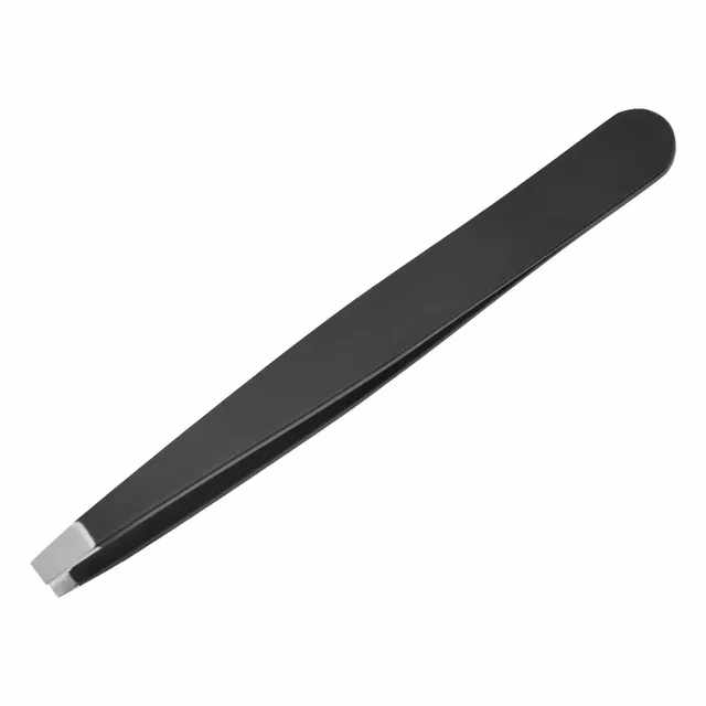
If you need to remove the BS from the enclosure, such as for antenna replacement, always adhere to the following instructions. There are two methods at your disposal, and for both, you'll require a hair dryer/Heatgun and Tweezers. We strongly advise against using tweezers with a different shape than those with flat and blunt ends, as shown in the image below. The use of differently shaped tweezers may result in damage to the BS itself, voiding the warranty.
Recommended Tweezer
 |
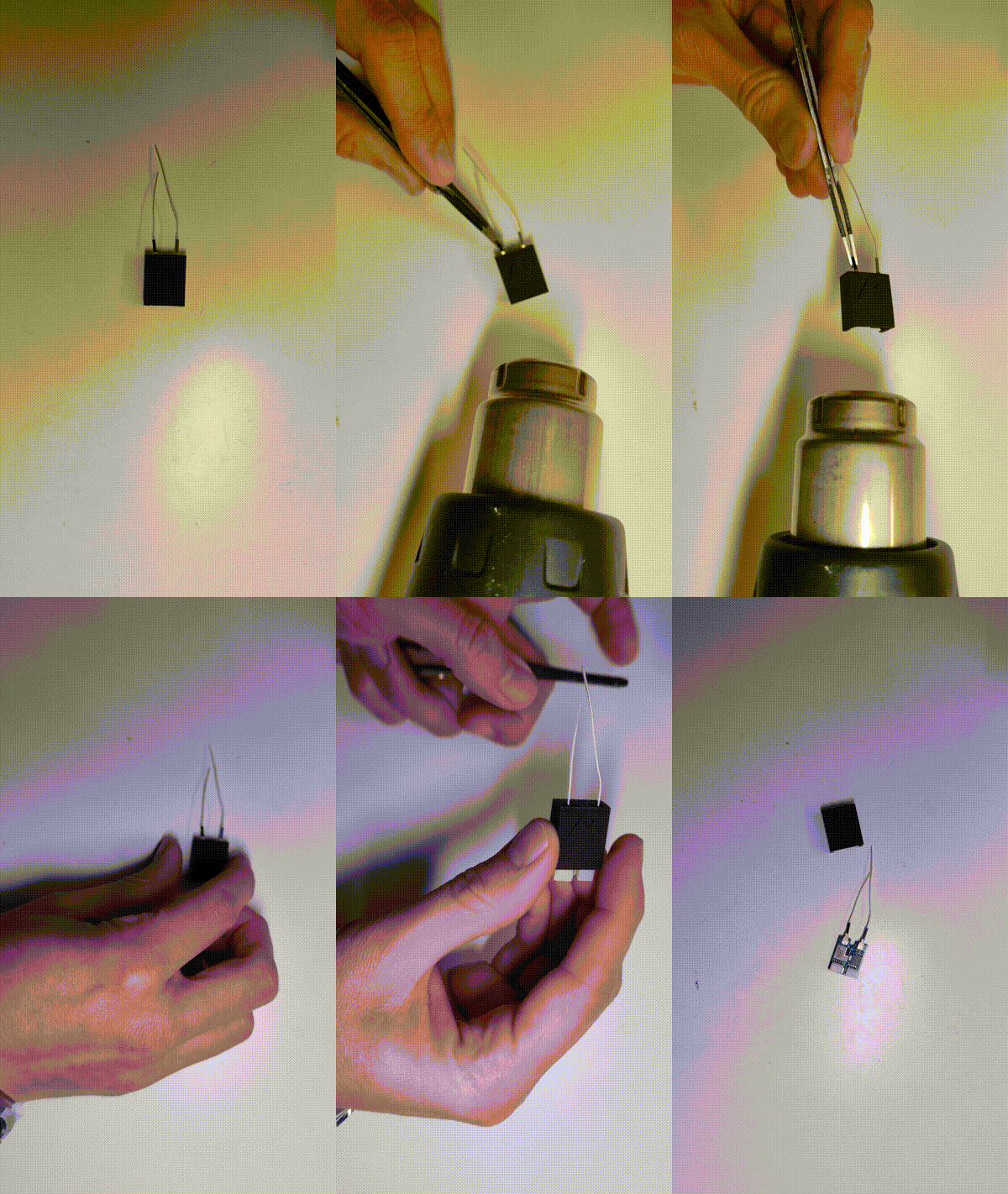
Method 1: Extrusion
Apply hot air to the enclosure, ensuring the temperature remains below 60 degrees Celsius, for a few seconds. As the package softens, use tweezers to gently push the BS through the hole located beneath the left antenna. A small cutout beneath the left antenna hole, visible when viewing the enclosure with the Dronetag logo on top, can guide you.
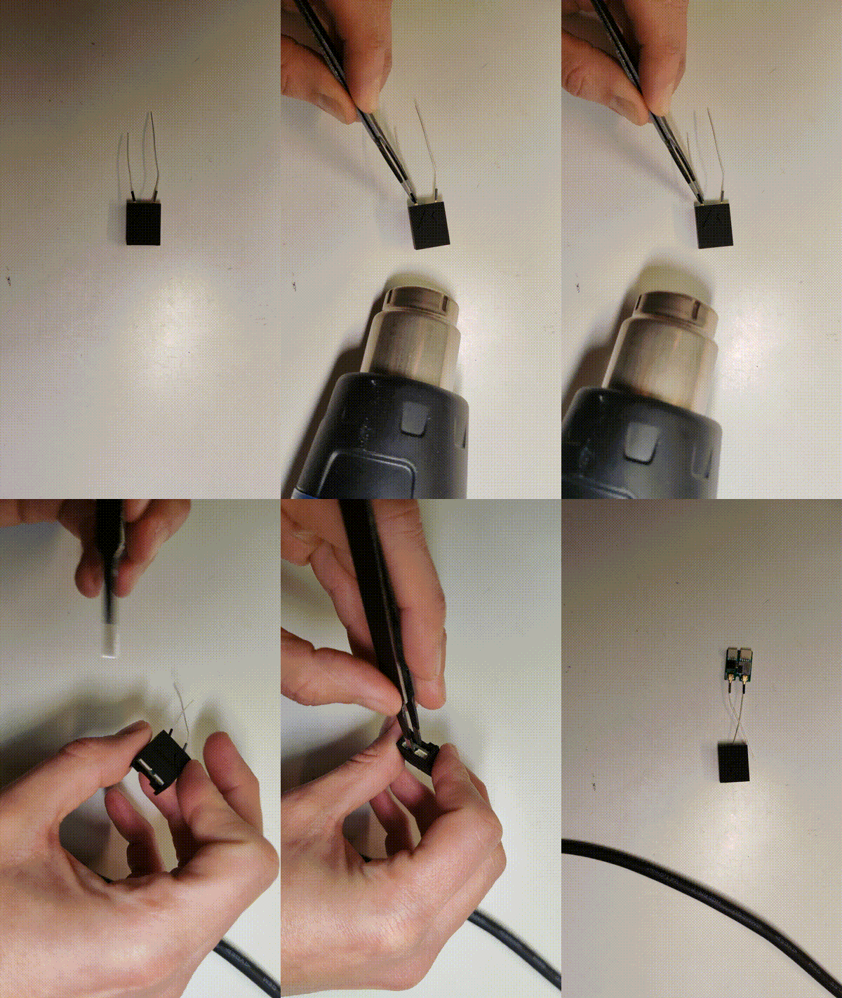
Method 2: Extraction
Delicately heat the package with a hair dryer or heat gun, keeping the temperature below 60 degrees Celsius. As the package softens, use tweezers to extract the BS. Use tweezers to grip the BS between the connectors; avoid holding the BS directly by the connectors to prevent damage.
Firmware Update
We are still adding new features to Dronetag BS. To follow the latest trends in our development, use this short guide to keep your firmware up to date.
Prerequisites
Before you start updating the firmware and during the process, please be sure to:
- Have your device charged to at least 50 % and turned on.
- Have a stable internet connection available (around 10 MB must be downloaded).
- Don't start the flight as the firmware cannot be updated in the Flight state.
- Don't restart, turn off or manipulate the device during the update.
Not following the guidelines above may lead to bricking the device.
Update via the Bluetooth
The Bluetooth update is a fast and easy option to update your BS firmware to the latest version. To update the firmware, our Dronetag mobile application must be used.
- Turn on the Bluetooth on your smartphone.
- Turn on the device and open the Dronetag mobile application.
- Go to Profile -> My Devices and select the device you would like to update.
- Click on Firmware Update to see if your device has the latest firmware version.
- If you have an update available, click on Download & Update.
- Read the instructions for the update procedure and confirm it with Proceed Update.
- Wait until the update is finished, which is indicated by a success message in the app.
Power Source Installation
The Dronetag BS unit is designed to operate with power inputs ranging from 3.3V to 17V. It employs a buck regulator mechanism to convert the incoming power to an internal voltage level. It's important to note that the power source chosen should be capable of handling peak currents of up to 50 mA at 3.3V.
The most commonly utilized sources for power input include the regulated voltage output from the flight controller. Alternatively, you have the option to utilize an aircraft battery, with support for up to 4S Li-Po configurations. For minimalistic usage, a compact external single-cell LiPo battery can also serve as a suitable power source for the device.
Using powerful batteries to power BS can potentially cause damage. Please read the Notice for products bought before 10/16/2023.
Where to Put Power Source?
Dronetag BS has two connectors on the front side. Both of these connectors can be used as a power input, however, the use depends on your scenario. We have prepared the right 3-pin connector as a plug & play for our Li-Po battery. The use of the 4-pin connector on the left side for power supply is of course also possible, but it is necessary to follow the Wiring diagram below.
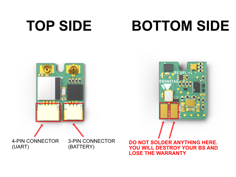
- Never supply both connectors with power input or you damage the device and connected power sources.
- Never use input voltage that falls outside the operating range of 3.3V to 17V or you damage the device and void the warranty.
- Never use the two soldering pads. Any attempt to use or solder anything onto these pads will result in irreversible damage to your BS device and will consequently void your warranty.
- BS lacks over polarity protection; connecting VCC and ground in reverse will result in irreversible damage.
Wiring Diagram
4-pin Connector (Placed on Left Side)
The connector placed on the left side of the Dronetag BS is a common JST SH 4-pin with UART interface with no flow control. This connector will also be used for support for Betaflight communication and Spektrum Telemetry XBUS in the future.
| Pin # | Name | Scheme Color | Description |
|---|---|---|---|
| 1 | VCC | Red | 3.3V to 17V. Directly connected to pin 1 at the 3-pin connector |
| 2 | UART RX | Green | Receive of the Dronetag device (3.3V logic - 5V tolerant) |
| 3 | UART TX | Blue | Transmit of the Dronetag device (3.3V logic - 5V tolerant) |
| 4 | Ground | Black | Ground connection |
VCC pin 1 is directly interconnected with VCC pin 1 at the 3-pin JST SH (the other connector)
3-pin Connector (Placed on Right Side)
The connector placed on the right side of the Dronetag BS is a common JST SH 3-pin for powering the device and for communication with SRXL2-compatible devices.
| Pin # | Name | Scheme Color | Description |
|---|---|---|---|
| 1 | VCC | Red | 3.3V to 17V. Directly connected to pin 1 at the 4-pin connector |
| 2 | RESERVED | Green | Reserved for SRXL2 support |
| 3 | Ground | Black | Ground connection |
VCC pin 1 is directly interconnected with VCC pin 1 at the 4-pin JST SH (the other connector)
Powering from Aircraft VIN
When choosing this type of power supply, you need to connect the BS with a cable to the power source. Always follow the rule that the power source chosen should be capable of handling peak currents of up to 50 mA at 3.3V.
Powered by External Battery
When an external battery is used, the Dronetag BS unit achieves full standalone functionality. Nonetheless, it's essential to consider the placement of the battery due to the current enclosure or heat shrink tube design limitations that prevent its accommodation. As a solution, you would need to create your custom enclosure, heat shrink tube, or mounting mechanism for the battery.
For your convenience, we offer a compact LiPo battery capable of powering the Dronetag BS unit for over 4 hours. This battery provides an excellent power source to ensure extended operational durations.
How to Use the Battery Charger
Operating with an input voltage of 5V, the charger maintains a charging current within the range of 50-200 mA. Adjusting the charging current is achievable through the soldering of specific jumpers on the charger's rear side. Connecting these jumpers together empowers you to enhance the charger's power output. It is imperative to underscore that any modifications in this regard are entirely your responsibility and should align with the specific battery you intend to charge. Please exercise the utmost caution, ensuring compatibility and implementing adequate safety measures during the modification process.
The board is also equipped with integrated circuits that offer protective functions, guarding the battery against overcharge, undercharge, and short circuits. Additionally, the board features a singular LED to indicate the ongoing charging status.
Notice for products bought before 10/16/2023
Dronetag BS is engineered to operate with power sources of up to 17 volts. However, when connecting a 4S battery with a voltage of 16.8 volts, there is a potential for a transient event to occur, overshooting by a factor of more than double voltage, exceeding 30 volts, leading to sparking and damaging the Dronetag BS.
This only affects products that were shipped before 10/16/2023.
Therefore, if you are powering the Dronetag BS directly from the battery, we suggest the following possible precautions:
-
Choose another way of power supply - e.g. from the balance connector (use only 1S or 2S).
-
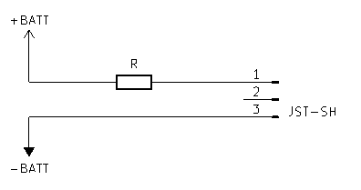
Limit the current voltage by adding a resistor to the power path to the BS (any from 4R7 to 120R will do).
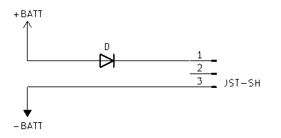
- Limit the transient by connecting a rectifier diode to the power path (e.g. 1N400x, 1N4148 will also do).
BS sent after 10/16/2023 will have this problem solved as a new revision of the BS will be introduced.
Attaching to the Drone
The BS can be attached to the drone in multiple ways, depending on your decision regarding the enclosure. Please check the section BS options.
If you use BS without an enclosure, you can attach it using an M2 screw mounting hole or double-sided adhesive tape or velcro.
If you decide to use BS with an enclosure, you can attach it using double-sided adhesive tape or velcro, no M2 holes are possible with the enclosure.
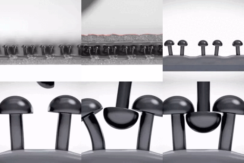
*When using velcro, we advise using a 3M Dual Lock with interlocking mushroom-shaped heads. They slide past each other to close with a snap and peel apart easily when you need to separate them by simply pulling the strips by hand.
Proper Location and attachment advice
Please watch out for these potential issues when looking for a suitable location and the type of attachment of the BS:
- If you are using a double-sided tape, please follow the manufacturer's recommendation, as some require some time curing for proper attachment.
- If mounted by double-sided tape, don't place BS over a curved surface because it might come off during flight.
- If mounted by double-sided tape, don't place BS on a soft material that can bend during mating (such as plastic covers). The double-sided tape may not hold properly.
- It is recommended to place BS in accessible locations. You should have the LEDs visible.
- When using an external antenna please do not choose a location with any metal surfaces and carbon tubing to prevent antenna detuning.
Disclaimer
We kindly advise that our company cannot assume responsibility for the installation of our product by the user or any potential loss incurred as a result. While we strive to provide comprehensive guidance and support, the responsibility for proper installation lies with the user. Should you require any further assistance or clarification, please do not hesitate to contact our customer support team. Your understanding is greatly appreciated.
LED Indications
The LED indicates the status of the device. Possible states are the following:

The LED is off = BS is not connected to power source
The LED is solid green = all RID data obtained, you are ready to fly. Green LED only shows when you are turning flight on and off via the app. Dronetag BS goes automatically into in flight mode when it is ready.
The LED is solid yellow. Device is waiting for a GNSS fix. If the Dronetag BS lost the fix during the flight, it will have solid yellow + blinking white until a GNSS fix is present again.
The LED blinks white every 3s. Device is broadcasting all Remote ID data and operating normally.
When the LED goes solid red, an error occurred and you must power cycle your module to recover into normal operation. Do not fly as the Remote ID function is not working properly.
Remote ID Compliancy
Dronetag BS can be used as a Remote ID enabler in the EU, USA, and all countries that accept ASTM F3411 or EN 4709-002 standards.
European Union:
Compliant with prEN 4709-002, which requires Direct Remote Identification for drones above 250 grams flying below 120 meters in the Specific category.
USA:
Dronetag BS is approved by the FAA (see DOC here) and compliant with ASTM F3411, which requires Broadcast Remote ID for all pilots flying out of FAA-recognized identification areas.
Global Compliance:
As BS only transmits data via Bluetooth, it is usable anywhere in the world. All countries using ASD-STAN or ASTM standards are supported. Check with your local aviation authority for the latest information on the applicability of Remote ID in your target regions.
Where can I find more details about Remote ID?
Maintenance & Troubleshooting
Firmware and software update
At Dronetag, we're committed to improving our products continually.
To ensure optimal performance, please make sure you're using the latest version of the Dronetag App and device firmware.
Kindly follow the provided instructions for updating your firmware.
Tips and procedures
If you are experiencing issues with BS not communicating, there are a few things you can try to troubleshoot the problem.
Firstly, check the Dronetag app to ensure that it is properly connected to the device. Make sure that the BS is turned on and within range of the app. Ensure that your mobile device with the Dronetag app has Bluetooth and location services enabled. If the BS device is not showing up in the app, try restarting both the device and the app and attempting to reconnect.
It is also a good idea to check the integration guide for your device once again to ensure that you have followed all the necessary steps for proper integration. Make sure that you have properly configured all settings and have followed all necessary steps for proper communication between the device, app, and controller. If the issue persists after trying the above steps, please don't hesitate to contact us for further assistance at support@dronetag.com
Regular maintenance schedule
Ensuring the safety of every flight is of utmost importance and part of a pilot's responsibility is to conduct pre-flight checks. Before takeoff, pilots should always check for any wiring issues to ensure correct functionality. In addition, pilots should also verify the attachment and functionality of all equipment, as well as the status of the LED light. By performing these critical checks, pilots can help prevent potential malfunctions and ensure the safety of all passengers on board.
How to upload assisted GNSS data
When using BS with Dronetag Wire antennas, please ensure to upload assisted GNSS data before each flight (the upload can be done via our app, check the short video). This step is needed due to the limited power of the Wire antennas.
If you are using BS with Dronetag Tube Antennas, or any other third-party antennas, we recommend uploading the Assisted GNSS data as well to ensure smooth performance without any degradation of performance.
Obtain diagnostic logs
To help resolve extraordinary issues, the Dronetag Support Team might request that you download diagnostic logs. If you haven’t received guidance from our support team and are experiencing an issue, please contact us at support@dronetag.com and also download your diagnostic logs for faster assistance.
- Turn on your device and open the Dronetag App.
- Go to your profile and select "My Devices."
- Choose your device, navigate to "Troubleshooting," and select "Obtain Diagnostic Logs."
These logs will be downloaded from your device and sent to our development team for review.
Glossary of terms
Remote ID (RID)
The Remote ID system enables drones to broadcast their location and identification details, which can be picked up by various participants in the airspace, such as pilots, authorities, and even the general public.
DRI
The Direct/Broadcast Remote ID refers to the use of Wi-Fi or Bluetooth technology to transmit Remote ID information to nearby areas. The nomenclature for this method differs depending on the location: in the EU, it is called Direct Remote ID, while in the US, it is referred to as Broadcast Remote ID.
ASD-STAN EN 4709-002
ASD-STAN EN 4709-002 is a European standard that provides guidelines for the development and implementation of Remote ID (identification) for unmanned aircraft systems (UAS), also known as drones. The standard specifies the technical requirements and performance criteria for Remote ID systems, which are used to identify and locate drones in flight. This information is transmitted to other airspace users, including authorities, pilots, and the general public. The goal of this standard is to improve the safety and security of drone operations and promote the integration of drones into the existing airspace system.
ASTM F3411-22
ASTM F3411-22 is a standard developed by the American Society for Testing and Materials (ASTM) that provides technical requirements for the design and performance of Remote ID (identification) systems for unmanned aircraft systems (UAS), also known as drones. The standard specifies the characteristics of the Remote ID message and the communication protocols that should be used for broadcasting the message. ASTM F3411-22 is intended to support the safe integration of drones into the national airspace system by enabling remote identification of UAS operations. The standard provides a consistent and interoperable framework for Remote ID systems to ensure that the information can be received and interpreted by other airspace participants, including authorities, pilots, and the general public. This standard is regularly reviewed and updated to keep pace with technological advancements and changing industry needs.
Limited Warranty
Dronetag products are warranted to be defect-free in material and workmanship one year after the purchase. For the duration of the warranty period, Dronetag, at its sole option, will repair or replace any product which fails in normal use. Such repairs or replacement will be made at no charge to the customer for parts or labour, provided that the customer shall be responsible for any transportation cost.
Restrictions
Warranty does not apply to cosmetic damage, consumable parts, damage caused by accident, abuse, misuse, water, fire or flood, damage caused by unauthorized servicing, or product that has been modified or altered.
Disclaimer
We kindly advise that our company cannot assume responsibility for the installation of our product by the user or any potential loss incurred as a result. While we strive to provide comprehensive guidance and support, the responsibility for proper installation lies with the user. Should you require any further assistance or clarification, please do not hesitate to contact our customer support team. Your understanding is greatly appreciated.
Warranty Service
Warranty repair service shall be provided directly by Dronetag. Proof of purchase for the product from Dronetag or an authorized reseller is required to obtain and better expedite warranty service. The customer is responsible for transportation costs involved in getting the unit to the Dronetag facility. It is recommended to use a shipping method with tracking and insurance.
Please email us at support@dronetag.com with a description of the problem you are experiencing. Also, please provide the model, serial number (if applicable), shipping address and a daytime contact number. You will be promptly contacted with further troubleshooting steps or return instructions.
Different Warranty Durations for Various Product Components
It is important to note that specific components, including batteries and others, may entail varying warranty terms due to their distinct usage and material properties. As per our warranty policy, the standard warranty duration for most products stands at one (1) year. However, it is pertinent to highlight that the warranty period for batteries is limited to six (6) months.
Post-Warranty Service
Besides warranty service, Dronetag also offers post-warranty repairs. Let us know at support@dronetag.com your problem, and we will try to do our best to find a solution for you.
Manufacturer
The device is designed and assembled in the Czech Republic. Use the following facility address for any shipment of warranty or repair items.
- Dronetag s.r.o., Benesovska 2270/34, 10100 Prague, Czech Republic
Firmware Changelog
Following is a detailed list of changes to the Dronetag BS firmware.
Please note that the changelog is very technical and can be hard to understand for non-technical users. You can use this changelog to check if a specific issue you are experiencing has been fixed in a newer firmware version, or to see what new small features are available.
If you find this information confusing, we recommend you check our What's new page instead, where we try to introduce the most important changes and features to all of our products.
Source pages
Every chapter of this document is a page of the Dronetag help site. Use these addresses to reach the latest version.
- 1Introductionhelp.dronetag.cz/dronetag-bs
- 2Specificationhelp.dronetag.cz/dronetag-bs/specification
- 3High-level List of Featureshelp.dronetag.cz/dronetag-bs/list-of-features
- 4Integration of Dronetag BShelp.dronetag.cz/dronetag-bs/integration
- 5Integration with Spektrum deviceshelp.dronetag.cz/dronetag-bs/spektrum-devices
- 6Usage Optionshelp.dronetag.cz/dronetag-bs/usage-options
- 7Heat-shrink Tube Installationhelp.dronetag.cz/dronetag-bs/heat-shrink-tube-installation
- 8Enclosure Installationhelp.dronetag.cz/dronetag-bs/enclosure-installation
- 9Firmware Updatehelp.dronetag.cz/dronetag-bs/firmware-update
- 10Power Source Installationhelp.dronetag.cz/dronetag-bs/power-source-installation/
- 11Notice for products bought before 10/16/2023help.dronetag.cz/dronetag-bs/power-source-installation/2023-10-notice
- 12Attaching to the Dronehelp.dronetag.cz/dronetag-bs/attaching-to-drone
- 13LED Indicationshelp.dronetag.cz/dronetag-bs/led-indications
- 14Remote ID Compliancyhelp.dronetag.cz/dronetag-bs/remote-id-compliancy
- 15Maintenance & Troubleshootinghelp.dronetag.cz/dronetag-bs/maintenance
- 16Glossary of termshelp.dronetag.cz/dronetag-bs/glossary-of-terms
- 17Limited Warrantyhelp.dronetag.cz/dronetag-bs/limited-warranty
- 18Downloadshelp.dronetag.cz/dronetag-bs/downloads
- 19Firmware Changeloghelp.dronetag.cz/dronetag-bs/firmware-changelog