
Integration Guide
- Document
- Dronetag DRI — Integration Guide
- Chapters
- 11
- Source
- help.dronetag.cz/print/dronetag-dri/integration
Retrofit Integration in the EU
This guide walks through the steps required to retrofit an existing drone with a Dronetag DRI to meet the requirements for Direct Remote Identification for drones in the Open category and Specific category in the EU. This guide does not describe integration as part of compliance with the C class for manufacturers.
Requirements
Make sure you have:
- Operator ID serial number (ANSI/CTA-2063-A format)
- Dronetag DRI module (recommended: U.FL antenna variant)
- Compatible antenna for the U.FL variant. The small testing antenna is included with a Dronetag DRI.
We recommend choosing a pre-approved antenna from our approved list of antennas. - Compatible cable to connect the DRI module to your flight controller. The example cable is included with a Dronetag DRI.
- Flight controller (e.g., Pixhawk or ArduPilot) installed in the drone.
- Tools to securely mount the DRI module to your drone: 3M Dual Lock / strong adhesive tape / Velcro or M2 screw.
- Smartphone supporting BLE 5.0 (for broadcast verification).
Required MAVLink messages
When used as a retrofit Remote ID for legacy drones, the Dronetag DRI composes Remote ID messages itself. The Operator ID is configured in the Dronetag App and stored in the device. However, the module still requires the following MAVLink messages from the flight controller to build valid RID broadcasts:
- MAVLINK_MSG_ID_ALTITUDE – altitude (PX4: pressure altitude).
- MAVLINK_MSG_ID_SCALED_PRESSURE – barometric pressure data.
- MAVLINK_MSG_ID_GPS_RAW_INT – GNSS position.
- MAVLINK_MSG_ID_SYSTEM_TIME – system time reference.
- MAVLINK_MSG_ID_GLOBAL_POSITION_INT – global position.
- MAVLINK_MSG_ID_HEARTBEAT – system status.
Step-by-Step Integration Guide
Mount the DRI on the Drone
- Look at your drone and find a suitable place for secure installation of the DRI module:
- DRI module with integrated antenna should be placed away from conductive materials like metal or carbon fiber.
- DRI module with U.FL antenna can be mounted on any material, but the antenna should not be covered with any conductive material like metal or carbon fiber.
- With a DRI module with U.FL antenna: position and secure the antenna in a place where it can freely transmit and receive signals.
- Use screws or adhesive tape to secure the DRI module to your drone.
- The DRI module should be mounted firmly and securely so it will not move during future flights.
- Look at your drone and find a suitable place for secure installation of the DRI module:
Connect DRI to Flight Controller
- Using the included cable or your custom cable, connect the DRI module and the flight controller:
- On the DRI module, choose Flight Controller port (Port C)
- On the flight controller, choose any unused telemetry port or serial interface port
- Please note the number of the telemetry/serial port to which you connected the DRI. It will be needed later.
noteFrom now on, we will demonstrate the guide steps on a Holybro Pix32 v5 flight controller as a reference.
The guide steps are identical or very similar for any other compatible flight controller.warningFollow the manufacturer's documentation for your flight controller to decide where you should connect your DRI module.
- Using the included cable or your custom cable, connect the DRI module and the flight controller:
Power On and Check LED Indicators
-
Power on the drone and check the DRI status:
- Yellow LED → Indicates basic power-up and standby. This is the expected state for a brand-new Dronetag DRI.
- Green LED → DRI is ready for takeoff. This means the DRI is already configured, and you should verify that the rest of the configuration is correct.
- If the LED occasionally flashes red, you may continue with the configuration. This can indicate a temporary mismatch between the configuration of the flight controller and the DRI, which will be resolved in the following steps.
-
See the LED indicator reference for the full color guide.
noteFor correct interpretation of the LED status, always check the indicator from a direct viewing angle.
When viewed from the side, the internal construction of the RGB LED may partially obscure one of its elements, which can make the color appear different.-
Configure DRI via Mobile App
If you are doing this for the first time, see the detailed walkthrough: DRI Configuration
- Use one of the supported mobile apps:
- Open the Dronetag Toolbox app.
- Select your DRI device from the device list.
- On the Identification screen, select the US identification and save.
- On the Configuration screen, check the following settings:
- Enable MAVLink flight start – True
- GNSS Input – MAVLink
- Pressure data input – MAVLink
- MAVLink Integration Type – Standard
- Controller Port Baud Rate – 115200
Connect the Flight Controller to PC
If you are doing this for the first time, see the detailed walkthrough: Connect to Flight Controller
A USB connection is the fastest and most reliable method to configure the flight controller. The alternative is to use a SiK Telemetry connection, which is slower than a USB connection, so be patient.
SiK TelemetryConnection using a SiK telemetry radio does not require a physical connection between the flight controller and PC, but it is much slower to work with than the USB method. How to use the Holybro SiK radio is described on the page Holybro SiK Radio V3 documentation.
SiK Telemetry warningIf you decide to connect a SiK Telemetry through the Port-Forwarding feature of the DRI, do not connect RTS/CTS lines between the DRI and the SiK radio.
Configure the Flight Controller
If you are doing this for the first time, see the detailed walkthrough: Flight Controller Setup
In your favorite configuration software for Flight Controller:
- Assign the correct serial port for the DRI in the FC parameters (symbol x in parameter names below). Use the noted number of the telemetry/serial port from the previous step:
SERIALx_PROTOCOL = MAVLink
- Set the serial port baud rate to 115200:
SERIALx_BAUD = 115200
- Turn off serial port flow control:
BRDSERx_RTSCTS = 0
Do you want more functions?If you want to use OpenDroneID with full integration (e.g., pre-flight checks, GNSS fix enforcement), check the Full Integration in USA.
- Assign the correct serial port for the DRI in the FC parameters (symbol x in parameter names below). Use the noted number of the telemetry/serial port from the previous step:
Confirm LED Status After FC Configuration
- Check the DRI status:
- Green LED → DRI is receiving valid MAVLink data and is ready for takeoff
- Yellow LED - Please check if your drone has GNSS lock.
- Red LED → Please check the cable connection between DRI and flight controller and ensure it is properly plugged in.
- See the LED indicator reference for the full color guide
noteFor correct interpretation of the LED status, always check the indicator from a direct viewing angle.
When viewed from the side, the internal construction of the RGB LED may partially obscure one of its elements, which can make the color appear different.- Check the DRI status:
Verify Broadcast in Mobile App
-
Use the Dronetag DroneScanner app on a BLE 5.0-capable device:
-
Confirm the transmission of Remote ID data:
- Serial number
- Drone location
- Timestamp
- Operator info (if applicable)
-
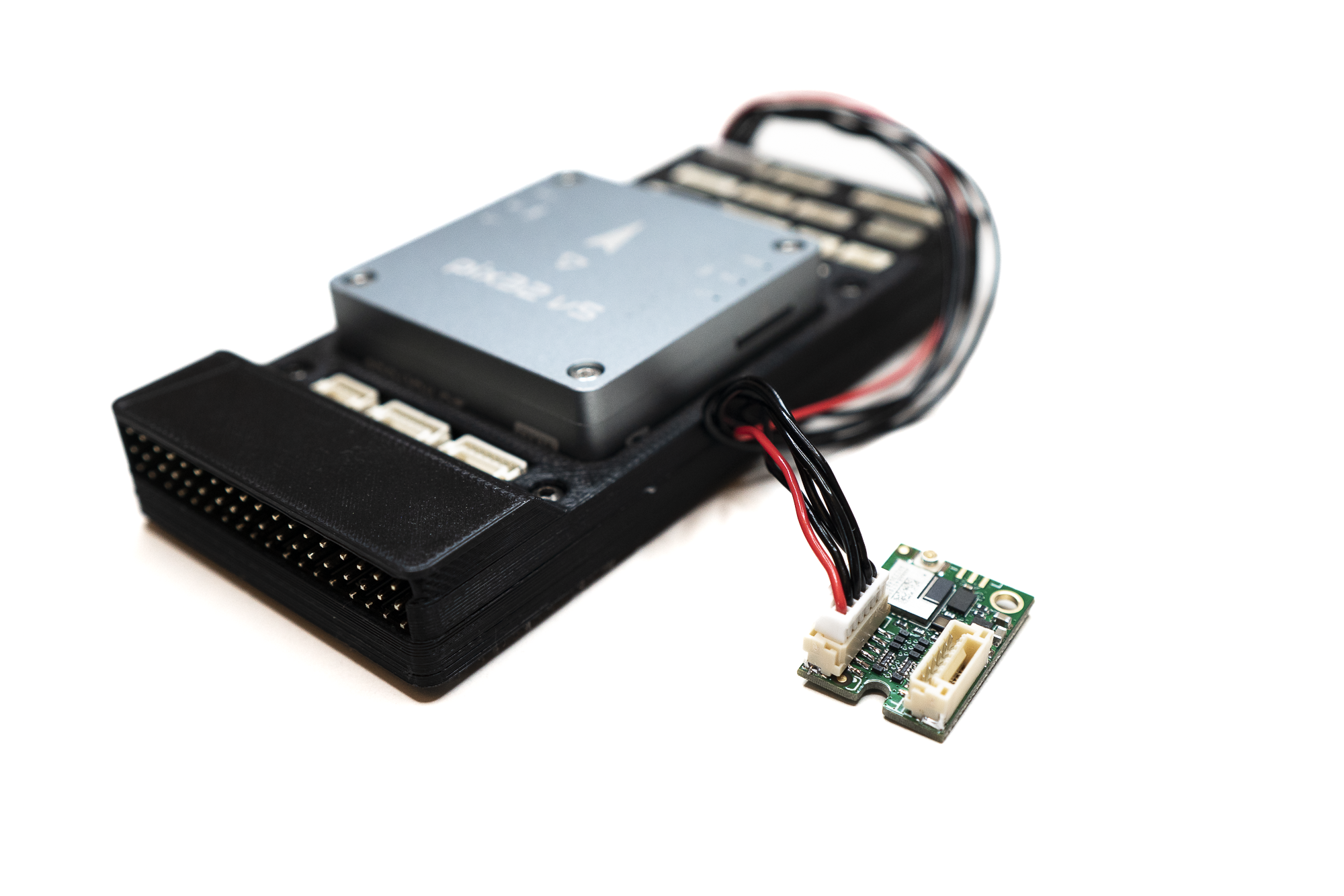
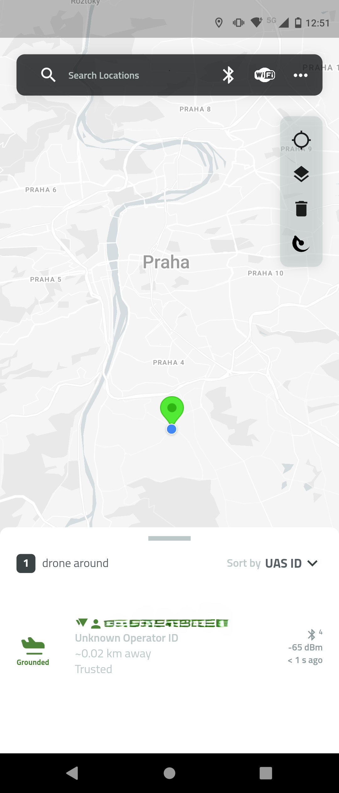
Done
At this point your Dronetag DRI is correctly installed and broadcasting your UAS Operator Registration Number.
This satisfies the EASA Remote ID requirement for legacy drones without C‑class marking.
The DRI module satisfies the remote identification requirement where applicable, but it does not grant permission for A2 or Specific category by itself. You must still meet pilot competency, drone class/marking, and (for Specific) hold an authorization or operate under STS conditions.
For complete EU rules and guidance, see the official EASA page: EASA – Civil Drones
Preflight Checklist
- Operator ID: UAS Operator Registration Number is valid and entered in the Dronetag App.
- DRI module: Properly mounted, powered, and antenna connected.
- Broadcast check: Remote ID signal verified in the Dronetag App before takeoff.
- GNSS lock: GPS fix acquired; position data is valid.
- Airspace & limits: Flight planned within EU rules (VLOS, max 120 m AGL, local restrictions).
- Pilot competency: Required training completed (A1/A3; STS/OA if applicable).
Retrofit Integration in the USA
Using Dronetag DRI for FAA Remote ID Broadcast Module Compliance
This guide walks through the steps required to retrofit an existing drone with the Dronetag DRI to meet the FAA's Remote ID Broadcast Module requirements under 14 CFR Part 89.
The FAA defines this mode for operators who modify drones that were not originally designed with Remote ID.
The DRI enables compliance by broadcasting the required identification data over Bluetooth without needing full OpenDroneID integration.
Requirements
Make sure you have:
- Remote ID serial number (ANSI/CTA-2063-A format)
- Dronetag DRI module (recommended: U.FL antenna variant)
- Compatible antenna for the U.FL variant. The small testing antenna is included with a Dronetag DRI.
We recommend choosing a pre-approved antenna from our approved list of antennas. - Compatible cable to connect the DRI module to your flight controller. The example cable is included with a Dronetag DRI.
- Flight controller (e.g., Pixhawk or ArduPilot) installed in the drone.
- Tools to securely mount the DRI module to your drone: 3M Dual Lock / strong adhesive tape / Velcro or M2 screw.
- Smartphone supporting BLE 5.0 (for broadcast verification).
Required MAVLink messages
When used as a retrofit Broadcast Module, the Dronetag DRI composes Remote ID messages itself. The Operator ID is configured in the Dronetag App and stored in the device. However, the module still requires the following MAVLink messages from the flight controller to build valid RID broadcasts:
- MAVLINK_MSG_ID_ALTITUDE – altitude (PX4: pressure altitude).
- MAVLINK_MSG_ID_SCALED_PRESSURE – barometric pressure data.
- MAVLINK_MSG_ID_GPS_RAW_INT – GNSS position.
- MAVLINK_MSG_ID_SYSTEM_TIME – system time reference.
- MAVLINK_MSG_ID_GLOBAL_POSITION_INT – global position.
- MAVLINK_MSG_ID_HEARTBEAT – system status.
Step-by-Step Integration Guide
Mount the DRI on the Drone
- Look at your drone and find a suitable place for secure installation of the DRI module:
- DRI module with integrated antenna should be placed away from conductive materials like metal or carbon fiber.
- DRI module with U.FL antenna can be mounted on any material, but the antenna should not be covered with any conductive material like metal or carbon fiber.
- With a DRI module with U.FL antenna: position and secure the antenna in a place where it can freely transmit and receive signals.
- Use screws or adhesive tape to secure the DRI module to your drone.
- The DRI module should be mounted firmly and securely so it will not move during future flights.
- Look at your drone and find a suitable place for secure installation of the DRI module:
Connect DRI to Flight Controller
- Using the included cable or your custom cable, connect the DRI module and the flight controller:
- On the DRI module, choose Flight Controller port (Port C)
- On the flight controller, choose any unused telemetry port or serial interface port
- Please note the number of the telemetry/serial port to which you connected the DRI. It will be needed later.
noteFrom now on, we will demonstrate the guide steps on a Holybro Pix32 v5 flight controller as a reference.
The guide steps are identical or very similar for any other compatible flight controller.warningFollow the manufacturer's documentation for your flight controller to decide where you should connect your DRI module.
- Using the included cable or your custom cable, connect the DRI module and the flight controller:
Power On and Check LED Indicators
-
Power on the drone and check the DRI status:
- Yellow LED → Indicates basic power-up and standby. This is the expected state for a brand-new Dronetag DRI.
- Green LED → DRI is ready for takeoff. This means the DRI is already configured, and you should verify that the rest of the configuration is correct.
- If the LED occasionally flashes red, you may continue with the configuration. This can indicate a temporary mismatch between the configuration of the flight controller and the DRI, which will be resolved in the following steps.
-
See the LED indicator reference for the full color guide.
noteFor correct interpretation of the LED status, always check the indicator from a direct viewing angle.
When viewed from the side, the internal construction of the RGB LED may partially obscure one of its elements, which can make the color appear different.-
Configure DRI via Mobile App
If you are doing this for the first time, see the detailed walkthrough: DRI Configuration
- Use one of the supported mobile apps:
- Open the Dronetag Toolbox app.
- Select your DRI device from the device list.
- On the Identification screen, select the US identification and save.
- On the Configuration screen, check the following settings:
- Enable MAVLink flight start – True
- GNSS Input – MAVLink
- Pressure data input – MAVLink
- MAVLink Integration Type – Standard
- Controller Port Baud Rate – 115200
Connect the Flight Controller to PC
If you are doing this for the first time, see the detailed walkthrough: Connect to Flight Controller
A USB connection is the fastest and most reliable method to configure the flight controller. The alternative is to use a SiK Telemetry connection, which is slower than a USB connection, so be patient.
SiK TelemetryConnection using a SiK telemetry radio does not require a physical connection between the flight controller and PC, but it is much slower to work with than the USB method. How to use the Holybro SiK radio is described on the page Holybro SiK Radio V3 documentation.
SiK Telemetry warningIf you decide to connect a SiK Telemetry through the Port-Forwarding feature of the DRI, do not connect RTS/CTS lines between the DRI and the SiK radio.
Configure the Flight Controller
If you are doing this for the first time, see the detailed walkthrough: Flight Controller Setup
In your favorite configuration software for Flight Controller:
- Assign the correct serial port for the DRI in the FC parameters (symbol x in parameter names below). Use the noted number of the telemetry/serial port from the previous step:
SERIALx_PROTOCOL = MAVLink
- Set the serial port baud rate to 115200:
SERIALx_BAUD = 115200
- Turn off serial port flow control:
BRDSERx_RTSCTS = 0
Do you want more functions?If you want to use OpenDroneID with full integration (e.g., pre-flight checks, GNSS fix enforcement), check the Full Integration in USA.
- Assign the correct serial port for the DRI in the FC parameters (symbol x in parameter names below). Use the noted number of the telemetry/serial port from the previous step:
Confirm LED Status After FC Configuration
- Check the DRI status:
- Green LED → DRI is receiving valid MAVLink data and is ready for takeoff
- Yellow LED - Please check if your drone has GNSS lock.
- Red LED → Please check the cable connection between DRI and flight controller and ensure it is properly plugged in.
- See the LED indicator reference for the full color guide
noteFor correct interpretation of the LED status, always check the indicator from a direct viewing angle.
When viewed from the side, the internal construction of the RGB LED may partially obscure one of its elements, which can make the color appear different.- Check the DRI status:
Verify Broadcast in Mobile App
-
Use the Dronetag DroneScanner app on a BLE 5.0-capable device:
-
Confirm the transmission of Remote ID data:
- Serial number
- Drone location
- Timestamp
- Operator info (if applicable)
-
Done
Your drone is now broadcasting as a Remote ID Broadcast Module using the Dronetag DRI.
This satisfies the FAA’s retrofit requirement under 14 CFR Part 89 for drones without built‑in Standard Remote ID.
A Broadcast Module is not Standard Remote ID. Flights must remain within Visual Line of Sight (VLOS) and comply with all other FAA rules. The module alone does not grant BVLOS or expanded operational privileges.
For complete FAA rules and guidance, see the official FAA page: Remote Identification of Drones – FAA
Preflight Checklist
- Module installed and powered securely on the drone
- Broadcast verified in the Dronetag App before takeoff
- Module serial number registered in FAA DroneZone with your drone
- GNSS lock acquired; position data valid
- Flight within VLOS and respecting FAA airspace restrictions
C‑class for Manufacturers in the EU
Integrating the Dronetag DRI module directly into a drone during manufacturing ensures that the aircraft can be certified as a C‑class UAS under EU Regulation 2019/945. This integration makes Remote ID a built‑in feature of the drone, not just an add‑on, and guarantees that the aircraft will always broadcast its identification data as required.
In practice, this means connecting the DRI module to the flight controller, ensuring continuous GNSS‑based position reporting, and verifying that the drone cannot take off if Remote ID is not functional. The details of wiring, firmware compatibility, and serial number handling are described in the following sections.
If you need any help certifying our device, please contact us at support@dronetag.com.
Certification in the EU
The integration of the Dronetag DRI module is only one part of the compliance process. In parallel with the integration steps described in this guide, manufacturers must complete the C‑class certification process under Regulation (EU) 2019/945. This process ensures that the drone can be legally placed on the EU market with a class identification label (C0–C6).
The certification process consists of the following main steps:
Technical Documentation
Prepare full technical documentation covering both design and production. This documentation must include at least:
- General description of the UAS (design, intended use, limitations)
- Detailed design drawings, schematics, and bill of materials
- Test reports (functional, safety, EMC, noise, Remote ID performance)
- Risk analysis and mitigation measures
- Production quality control procedures
- Copies of instructions and user manuals supplied with the product
The documentation must be sufficient to demonstrate compliance with all applicable essential requirements of Regulation (EU) 2019/945.
Conformity Assessment
Select and complete the appropriate conformity assessment procedure depending on the drone class and your production setup:
-
Module A (Internal production control) – available only for C0 class drones. As a manufacturer, you can self‑declare conformity without involving a Notified Body, provided you prepare full technical documentation and carry out your own internal testing to prove compliance.
-
Module B (EU‑type examination) – the Notified Body tests and certifies that your drone’s design meets all essential requirements. For you, this means submitting a representative sample and documentation for independent evaluation.
-
Module C (Conformity to type) – this follows Module B. As a manufacturer, you must ensure that every unit you produce matches the approved type and keep records to demonstrate this consistency.
-
Module H (Full quality assurance) – the Notified Body audits your entire quality management system. If you choose this route, you need to maintain a robust quality system covering both design and production, which will be regularly reviewed.
For drones in classes C1, C2, C3 (and higher), Module A is not available. In these cases, cooperation with a Notified Body is mandatory. A Notified Body is an independent certification organization designated by an EU Member State and listed in the NANDO database.
EU Declaration of Conformity
After successful conformity assessment, the manufacturer must issue an EU Declaration of Conformity. This document states that the product complies with Regulation (EU) 2019/945 and the relevant harmonized standards (e.g. EN 4709‑002 for Remote ID). The Declaration must be signed by the manufacturer’s authorized representative and kept available for market surveillance authorities.
CE Marking and C‑class Label
Once conformity is confirmed, affix the CE marking and the correct C‑class identification label (C0–C6) to the aircraft. These markings must be visible, legible, and indelible. Without CE marking and C‑class labeling, the drone cannot be legally placed on the EU market.
Production Serials and Traceability
Each manufactured unit must carry a unique Remote ID serial number in the ICAO‑compliant ANSI/CTA‑2063‑A format. Manufacturers must maintain detailed records of:
- Production batches
- Assigned serial numbers
- Firmware configurations
These records must be preserved for conformity assessment and for potential audits by market surveillance authorities.
Integration Architecture
The integration relies on a data flow between the Ground Control Station (GCS), the flight controller, and the Dronetag DRI module:
- The GCS software (e.g., QGroundControl, Mission Planner) provides operator information and status messages using the OpenDroneID MAVLink message set.
- The flight controller relays these messages to the DRI module, adding live telemetry such as GNSS position and system status.
- The DRI module broadcasts the combined Remote ID data over BLE/Wi‑Fi in compliance with EU harmonized standards.
- If the GCS link is lost, the flight controller continues to provide the last valid data to the DRI, ensuring uninterrupted broadcast.
This architecture ensures that Remote ID is always active and that the drone cannot take off if the DRI or GNSS is not functional.
Key Integration Requirements
Firmware Compatibility
To integrate the Dronetag DRI module, the flight controller must run firmware that supports the OpenDroneID message set. How to create the required firmware for basic purposes with OpenDroneID support is described later in this Guide.
The firmware must be built in a tamper‑resistant way and reliably publish the required Remote ID messages. End users must not be able to disable or alter this functionality.
MAVLink messages
When integrated with an autopilot supporting OpenDroneID (ArduPilot, PX4), the Dronetag DRI exchanges MAVLink messages. The autopilot provides flight data, and DRI acts as the broadcast interface. All required messages and their meanings are listed below, with the most important ones described in dedicated sections.
Messages required from the autopilot
- MAVLINK_MSG_ID_ALTITUDE – altitude (PX4: pressure altitude).
- MAVLINK_MSG_ID_SCALED_PRESSURE – barometric pressure data.
- MAVLINK_MSG_ID_GPS_RAW_INT – GNSS position.
- MAVLINK_MSG_ID_SYSTEM_TIME – system time reference.
- MAVLINK_MSG_ID_GLOBAL_POSITION_INT – global position.
- MAVLINK_MSG_ID_HEARTBEAT – system status.
Additional messages from OpenDroneID set
- OPEN_DRONE_ID_BASIC_ID – drone identification (overrides DRI default ID).
- OPEN_DRONE_ID_LOCATION – drone position.
- OPEN_DRONE_ID_SYSTEM – system information.
- OPEN_DRONE_ID_OPERATOR_ID – operator identification (must come from autopilot, not DRI app).
- OPEN_DRONE_ID_ARM_STATUS – confirms DRI decoded all data correctly and drone is ready to arm (includes error messages if not).
Serial Number Handling (OPEN_DRONE_ID_BASIC_ID)
The drone must transmit its own UAS serial number in the ICAO‑compliant ANSI/CTA‑2063‑A format. This value overrides the default DRI serial number.
We strongly recommend hardcoding the serial number into the flight controller firmware (protected parameter or EEPROM), not relying on GCS runtime configuration. This ensures the value is stored in a tamper‑free location and cannot be modified by the end user.
If you use a pre‑prepared integration method (for example, ArduPilot builds with OpenDroneID support), you must verify that the firmware truly stores the serial number in a protected, tamper‑free memory area and that it cannot be changed by the operator after production.
Arming and Failsafe (OPEN_DRONE_ID_ARM_STATUS)
The drone must refuse takeoff if the DRI module is disconnected, misconfigured, or if no valid GNSS fix is available. This requirement comes directly from the harmonized standard EN 4709‑002, which supports compliance with EU Regulation 2019/945 for C‑class drones.
The purpose of this requirement is to ensure that Remote ID is always active before and during flight. Manufacturers must implement a pre‑flight check that blocks arming if Remote ID or GNSS is not functional, and verify this behavior during conformity assessment testing.
GNSS Lock and Continuity
A valid GNSS fix must be established before arming the drone. The system must maintain continuous GNSS position reporting throughout the entire flight.
This requirement ensures that the Remote ID broadcast always contains accurate and up‑to‑date location data, as mandated by EN 4709‑002 under EU Regulation 2019/945.
If GNSS reception is lost, the drone must trigger the defined failsafe behavior — for example, blocking arming while on the ground, or executing Return‑to‑Home (RTH) or controlled landing during flight. Manufacturers must verify this behavior during conformity assessment testing.
Broadcast Continuity
The Remote ID broadcast must remain uninterrupted throughout the entire flight. If the Ground Control Station (GCS) stops providing updates, the flight controller must continue sending the last valid data to the DRI module.
This requirement ensures that the Remote ID signal is always active and compliant with EN 4709‑002 under EU Regulation 2019/945. Manufacturers must verify during conformity assessment that the broadcast does not stop even in case of GCS link loss or temporary communication issues.
Antenna Placement and EMC
The DRI module and its antenna must be installed in a way that guarantees reliable signal transmission. They must not be shielded by conductive materials such as carbon fiber or metal parts of the airframe.
The antenna should be firmly secured to prevent detuning, cable strain, or damage during flight. Manufacturers must verify electromagnetic compatibility (EMC) as part of the conformity assessment, ensuring that the Remote ID broadcast is not degraded by other onboard electronics.
Production Serials and Traceability
Each manufactured unit must carry a unique Remote ID serial number.
This identifier must follow the ICAO‑compliant ANSI/CTA‑2063‑A format and be permanently assigned to the aircraft during production.
Manufacturers are responsible for maintaining detailed records of production batches, assigned serial numbers, and firmware configurations.
These records must be preserved for conformity assessment and potential market surveillance by authorities.
It is the manufacturer’s duty to verify that:
- every unit leaving production has a valid and unique Remote ID serial number,
- the serial number is correctly stored in tamper‑free memory,
- and the production documentation is complete and auditable.
If you are building or modifying your own flight controller firmware, please see the Custom Firmware Integration Guide.
It explains which MAVLink and OpenDroneID messages must be published to the Dronetag DRI, which identifiers must be hardcoded in firmware (such as Remote ID serial numbers), and which values should remain configurable (such as Operator ID in the EU or operator location in the USA).
This guide also points to a reference implementation on GitHub and describes how to verify correct broadcasts using the DroneScanner app.
Step-by-Step Integration Guide
You will need:
- Flight controller (e.g. Pixhawk or ArduPilot) programmed with unique firmware created in section Unique firmware for Flight Controller
- Dronetag DRI module (recommended: U.FL antenna variant)
- Compatible antenna for the U.FL variant. The small testing antenna is included with a Dronetag DRI.
We recommend choosing a pre-approved antenna from our approved list of antennas. - Compatible cable to connect the DRI module to your flight controller. The example cable is included with a Dronetag DRI.
- Tools to securely mount the DRI module to your drone: 3M Dual Lock / strong adhesive tape / Velcro or M2 screw.
- Smartphone supporting BLE 5.0 (for broadcast verification).
Unique firmware for Flight Controller
To integrate the Dronetag DRI module with your flight controller, you’ll need to build a unique firmware tailored to your hardware and compliance needs. The process depends on whether you're using ArduPilot or Pixhawk/PX4 firmware.
Pixhawk / PX4 Firmware
Pixhawk flight controllers running PX4 firmware currently offer experimental support for Remote ID only. However, full Open Drone ID integration is not yet supported at the time of writing. For details on current capabilities and supported hardware, refer to the PX4 Remote ID documentation.
We recommend checking this page regularly, as PX4 development is active and support for full Open Drone ID integration may be added in future releases.
ArduPilot firmware
If your flight controller runs ArduPilot, follow the official ArduPilot guide for OpenDroneID firmware creation. This guide includes instructions for:
- Enabling tamper-resistant features
- Compiling firmware with specific board IDs
- Configuring MAVProxy for testing
Before proceeding, integrators should verify—based on the documentation of their flight controller manufacturer and the firmware used—whether the firmware publishes the required Remote ID messages listed earlier in the section Key Integration Requirements.
Mount the DRI on the Drone
- Look at your drone and find a suitable place for secure installation of the DRI module:
- DRI module with integrated antenna should be placed away from conductive materials like metal or carbon fiber.
- DRI module with U.FL antenna can be mounted on any material, but the antenna should not be covered with any conductive material like metal or carbon fiber.
- With a DRI module with U.FL antenna: position and secure the antenna in a place where it can freely transmit and receive signals.
- Use screws or adhesive tape to secure the DRI module to your drone.
- The DRI module should be mounted firmly and securely so it will not move during future flights.
- Look at your drone and find a suitable place for secure installation of the DRI module:
Connect DRI to Flight Controller
- Using the included cable or your custom cable, connect the DRI module and the flight controller:
- On the DRI module, choose Flight Controller port (Port C)
- On the flight controller, choose any unused telemetry port or serial interface port
- Please note the number of the telemetry/serial port to which you connected the DRI. It will be needed later.
noteFrom now on, we will demonstrate the guide steps on a Holybro Pix32 v5 flight controller as a reference.
The guide steps are identical or very similar for any other compatible flight controller.warningFollow the manufacturer's documentation for your flight controller to decide where you should connect your DRI module.
- Using the included cable or your custom cable, connect the DRI module and the flight controller:
Power On and Check LED Indicators
-
Power on the drone and check the DRI status:
- Yellow LED → Indicates basic power-up and standby. This is the expected state for a brand-new Dronetag DRI.
- Green LED → DRI is ready for takeoff. This means the DRI is already configured, and you should verify that the rest of the configuration is correct.
- If the LED occasionally flashes red, you may continue with the configuration. This can indicate a temporary mismatch between the configuration of the flight controller and the DRI, which will be resolved in the following steps.
-
See the LED indicator reference for the full color guide.
noteFor correct interpretation of the LED status, always check the indicator from a direct viewing angle.
When viewed from the side, the internal construction of the RGB LED may partially obscure one of its elements, which can make the color appear different.-
Configure DRI via Mobile App
If you are doing this for the first time, see the detailed walkthrough: DRI Configuration
- Use one of the supported mobile apps:
- Open the Dronetag Toolbox app.
- Select your DRI device from the device list.
- On the Identification screen, configure the EU profile and confirm that the aircraft’s UAS serial number (ANSI/CTA‑2063‑A) is used as the Basic ID.
- On the Configuration screen, check the following settings:
- Enable MAVLink flight start – True
- GNSS Input – MAVLink
- Pressure data input – MAVLink
- MAVLink Integration Type – OpenDroneId
- Controller Port Baud Rate – 115200
Connect the Flight Controller to PC
If you are doing this for the first time, see the detailed walkthrough: Connect to Flight Controller
A USB connection is the fastest and most reliable method to configure the flight controller. The alternative is to use a SiK Telemetry connection, which is slower than a USB connection, so be patient.
SiK TelemetryConnection using a SiK telemetry radio does not require a physical connection between the flight controller and PC, but it is much slower to work with than the USB method. How to use the Holybro SiK radio is described on the page Holybro SiK Radio V3 documentation.
SiK Telemetry warningIf you decide to connect a SiK Telemetry through the Port-Forwarding feature of the DRI, do not connect RTS/CTS lines between the DRI and the SiK radio.
Configure the Flight Controller
If you are doing this for the first time, see the detailed walkthrough: Flight Controller Setup
- Assign the correct serial port for the DRI in the FC parameters (symbol x in parameter names below). Use the noted number of the telemetry/serial port from the previous step:
SERIALx_PROTOCOL = MAVLink
- Set the serial port baud rate to 115200:
SERIALx_BAUD = 115200
- Turn off serial port flow control:
BRDSERx_RTSCTS = 0
- Enable OpenDroneID support:
DID_ENABLE = Enabled
- Set the port to which the DRI is connected:
DID_MAVPORT = x
infoTo set up your flight controller to support OpenDroneID, the flight controller must run unique firmware. See the section Unique firmware for Flight Controller.
- Assign the correct serial port for the DRI in the FC parameters (symbol x in parameter names below). Use the noted number of the telemetry/serial port from the previous step:
Configure the Ground Control Station
- Open your ground control station app that supports OpenDroneID.
- Configure the OpenDroneID support in the ground station app for EU operation:
- Region of Operation – EU
- No need to transmit operator GNSS location
infoTo use the OpenDroneID support of your ground station app, your flight controller must also support OpenDroneID. See the section Unique firmware for Flight Controller.
Confirm LED Status After FC Configuration
- Check the DRI status:
- Green LED → DRI is receiving valid MAVLink data and is ready for takeoff
- Yellow LED - Please check if your drone has GNSS lock.
- Red LED → Please check the cable connection between DRI and flight controller and ensure it is properly plugged in.
- See the LED indicator reference for the full color guide
noteFor correct interpretation of the LED status, always check the indicator from a direct viewing angle.
When viewed from the side, the internal construction of the RGB LED may partially obscure one of its elements, which can make the color appear different.- Check the DRI status:
Verify Broadcast in Mobile App
-
Use the Dronetag DroneScanner app on a BLE 5.0-capable device:
-
Confirm the transmission of Remote ID data:
- Serial number
- Drone location
- Timestamp
- Operator info (if applicable)
-
Done
At this point your drone design meets the technical requirements of Remote ID integration. To complete compliance as a manufacturer under EU Regulation 2019/945, you must finalize the C‑class certification process:
Technical Documentation
Prepare full technical documentation covering design, testing, and analysis of the drone and its integrated Remote ID system. This documentation must be sufficient to demonstrate compliance with all applicable essential requirements.
Conformity Assessment
Select and complete the appropriate conformity assessment procedure (Module A, B+C, or H) depending on your production setup and category of the drone.
Important: For drones in classes C1, C2, C3 (and higher), Module A (self-declaration) is not available. In these cases, the manufacturer must cooperate with a Notified Body:
- Module B (EU-type examination): the Notified Body tests and certifies that the drone design meets all essential requirements.
- Module C (conformity to type): the manufacturer ensures that every produced unit conforms to the approved type.
- Module H (full quality assurance): the Notified Body audits the manufacturer’s quality system covering design and production.
This independent assessment is required by Regulation (EU) 2019/945 to guarantee compliance with safety, Remote ID, geo-awareness, and other mandatory features. Only after successful assessment with a Notified Body can the manufacturer issue the EU Declaration of Conformity and affix the CE marking with the correct C‑class label.
EU Declaration of Conformity
Issue an EU Declaration of Conformity stating that the product complies with Regulation (EU) 2019/945 and the relevant harmonized standards (including EN 4709‑002 for Remote ID). The full list of harmonized standards is published by the European Commission and can be found here: Official list of harmonized standards for drones – European Commission
CE Marking and C‑class Label
Affix the CE marking and the correct C‑class identification label (C0–C6) to the aircraft. These markings must be visible, legible, and indelible.
Production Serials and Traceability
Ensure that each manufactured unit carries a unique Remote ID serial number. Maintain detailed records of production batches, assigned serials, and firmware configurations for market surveillance and audits.
Until CE marking and C‑class labeling are completed, the drone is not legally a C‑class UAS and cannot be placed on the EU market.
For detailed guidance, see EASA – Placing a drone on the market with class identification label.
If you need any help certifying our device, please contact us at support@dronetag.com.
Standard Remote ID for Manufacturers in the USA
To achieve Standard Remote ID compliance in the United States under FAA 14 CFR Part 89, the Dronetag DRI module must be integrated with the flight controller using the MAVLink OpenDroneID message set. This integration mode is mandatory for manufacturers producing drones classified as Standard Remote ID Drones.
Certification in the USA
In addition to integrating the Dronetag DRI module, manufacturers targeting the US market must complete two parallel certification processes: FAA Standard Remote ID compliance and FCC equipment authorization. These steps are straightforward if you follow the official guidance.
If you need any help certifying our device, please contact us at support@dronetag.com.
FAA Standard Remote ID compliance (14 CFR Part 89)
To market a drone as a Standard Remote ID Drone, you must:
- Use an FAA‑accepted Means of Compliance (MoC). This is the method that shows your design meets the Remote ID performance requirements. You can either adopt an existing accepted MoC (e.g. ASTM F3411) or submit your own for FAA acceptance.
- File a Declaration of Compliance (DoC). This is a formal statement to the FAA that your production units follow an accepted MoC. Without FAA acceptance of your DoC, your drone is not legally considered a Standard Remote ID aircraft.
- Assign valid Remote ID serial numbers. Each unit must carry a unique serial in the ANSI/CTA‑2063‑A format. These serials are registered in the FAA DroneZone when you submit your DoC.
Unlike EU C0 class, there is no “self‑declaration” path for Standard Remote ID drones in the US. You must go through the FAA’s MoC/DoC process.
Means of Compliance (MoC)
To certify a drone as a Standard Remote ID aircraft in the United States, manufacturers must adopt an FAA‑accepted Means of Compliance. The most common is ASTM F3411, which defines the Remote ID performance requirements.
Testing against this standard is performed according to ASTM F3586‑22 (Standard Practice for Remote ID Means of Compliance to ASTM F3411). These procedures are mandatory and carried out by accredited laboratories. Manufacturers do not need to implement the procedures themselves, but must ensure their devices pass them. Reference: ASTM F3586‑22.
As part of the MoC submission, manufacturers must also provide a Compliance Matrix. This document maps each regulatory requirement to the corresponding implementation or evidence in the product. It serves as a structured checklist for both the manufacturer and the FAA to verify that all obligations are covered.
We provide a ready‑to‑use Dronetag DRI - ASTM F3411‑22a Compliance Matrix to simplify this process: Dronetag DRI - ASTM F3411‑22a Compliance Matrix.
For verification during development, we recommend:
- nRF Sniffer Tool – to capture and analyze BLE broadcasts.
- DroneScanner app – to confirm that Remote ID messages are transmitted correctly on a mobile device.
- Drone Scanner on Google Play
- Drone Scanner on Apple Store
iOS devices are not recommended, as they do not support Bluetooth 5 Long Range (Coded PHY)
Declaration of Compliance (DoC)
The Declaration of Compliance (DoC) is a formal submission to the FAA confirming that your production units conform to an accepted Means of Compliance (MoC).
It is a legal attestation that your drone design, manufacturing process, and final product meet all Remote ID performance requirements defined in the MoC.
A DoC can only be filed after your MoC has been reviewed and accepted by the FAA. This includes the submission of a complete Compliance Matrix and any supporting documentation required by the chosen standard (e.g. ASTM F3411).
Once accepted, the FAA assigns a unique Remote ID FRN (Federal Registration Number) to your product line. This FRN is used to register Remote ID serial numbers in the FAA DroneZone portal and links your production units to the approved compliance path.
Key points:
- The DoC must be submitted by the manufacturer or authorized representative.
- It applies to a specific product line or configuration — changes in hardware or firmware may require a new DoC.
- The FAA may request additional documentation or clarification before accepting the DoC.
- Until the DoC is accepted, the drone cannot be marketed or operated as a Standard Remote ID aircraft in the United States.
For official guidance, refer to FAA Advisory Circular AC 89‑2.
Remote ID serial assignment
Each unit must carry a unique serial number in the ANSI/CTA‑2063‑A format. We recommend hard‑coding the serial into the flight controller firmware to prevent tampering. These serials are registered in the FAA DroneZone when submitting your DoC.
Serial numbers must conform to the ICAO-compliant ASTM format:
<ICAO Manufacturer Code> + <Unique Device Serial>
Example: 1596ABC1234567890
As a drone manufacturer, you must request an ICAO prefix for your organization. See: ICAO - Remote ID Number Registration
FCC equipment authorization (47 CFR Part 2, Subpart J)
Any drone or module with RF transmitters must be authorized by the FCC before it can be marketed or imported into the United States.
There are two approval paths:
- Certification – required for most intentional radiators (e.g. Wi‑Fi, Bluetooth, telemetry). Testing must be done by an FCC‑recognized accredited lab, and approval is granted by a Telecommunications Certification Body (TCB).
- Supplier’s Declaration of Conformity (SDoC) – available for some devices, with testing at a competent lab, but without TCB involvement.
Once approved, certified devices receive an FCC ID, which must be printed on the product and included in the user manual. For SDoC, you must provide a compliance statement with the product and keep records available for inspection.
Simplified integration using “Contains FCC ID”
If your drone integrates a module that already has FCC Certification, you may use the “Contains FCC ID” labeling method. This allows you to avoid re‑certifying the entire drone, as long as:
- The module is used in accordance with its original certification.
- The antenna type and gain match the approved configuration.
The Dronetag DRI module integrates the u-blox ANNA-B4 radio, which is certified under the FCC ID:
FCC ID: XPYANNAB4
(This must appear on the product label or documentation of any device that incorporates the module.)
This shortcut is especially useful for manufacturers using pre‑certified Remote ID modules like Dronetag DRI.
Preapproved antennas
FCC Certification is always tied to specific antenna types and configurations. Using a different antenna than the one listed in the original certification may invalidate the authorization. We provide a list of preapproved antennas compatible with Dronetag DRI modules: View preapproved antenna list
The small antenna included with Dronetag DRI or Dronetag DRI with internal antenna is intended for testing only and may not meet FCC EIRP limits for final certification. For preapproved antenna list see: View preapproved antenna list
By completing both FAA and FCC processes in parallel with integration, you ensure your drone can be legally marketed in the US as a Standard Remote ID product.
Integration Architecture
The integration relies on a collaborative data relay between the Ground Control Station (GCS), the drone, and the Dronetag DRI transmitter as follows:
- The GCS software (e.g., QGroundControl or Mission Planner) sends OpenDroneID MAVLink messages (e.g., operator info, emergency status) to the flight controller.
- The flight controller relays these messages to the Dronetag DRI with updated target component/system IDs.
- If the GCS connection is lost, the drone continues to send the most recent known values to the DRI to maintain broadcast continuity.
This ensures Remote ID broadcasts are maintained in accordance with FAA expectations for Standard RID drones, even in loss-of-link scenarios.
This also means that the aircraft is not permitted to take off (pre-flight checks will fail) without a functional Dronetag DRI, or when the connection with the DRI or GNSS is lost. These pre-flight checks should not be possible to bypass.
Key Integration Requirements
The flight controller should run firmware compatible with the OpenDroneID system. There are several requirements that must be met; otherwise, full integration in terms of Standard Remote ID compliance in the United States cannot be achieved.
MAVLink messages
When integrated with an autopilot supporting OpenDroneID (ArduPilot, PX4), the Dronetag DRI exchanges MAVLink messages. The autopilot provides flight data, and DRI acts as the broadcast interface. All required messages and their meanings are listed below, with the most important ones described in dedicated sections.
Messages required from the autopilot
- MAVLINK_MSG_ID_ALTITUDE – altitude (PX4: pressure altitude).
- MAVLINK_MSG_ID_SCALED_PRESSURE – barometric pressure data.
- MAVLINK_MSG_ID_GPS_RAW_INT – GNSS position.
- MAVLINK_MSG_ID_SYSTEM_TIME – system time reference.
- MAVLINK_MSG_ID_GLOBAL_POSITION_INT – global position.
- MAVLINK_MSG_ID_HEARTBEAT – system status.
Additional messages from OpenDroneID set
- OPEN_DRONE_ID_BASIC_ID – drone identification (overrides DRI default ID).
- OPEN_DRONE_ID_LOCATION – drone position.
- OPEN_DRONE_ID_SYSTEM – system information.
- OPEN_DRONE_ID_OPERATOR_ID – operator identification (must come from autopilot, not DRI app).
- OPEN_DRONE_ID_ARM_STATUS – confirms DRI decoded all data correctly and drone is ready to arm (includes error messages if not).
Serial Number Handling (OPEN_DRONE_ID_BASIC_ID)
- The drone must transmit its own serial number to the DRI using the OPEN_DRONE_ID_BASIC_ID message. This value overrides the default DRI serial number.
- We strongly recommend hardcoding the serial number into the flight controller firmware, using a protected parameter or EEPROM setting to make it unchangeable.
- While sending the serial number from the GCS is possible, it is not recommended due to a higher risk of tampering or configuration errors.
Serial numbers must conform to the ICAO-compliant ASTM format as described in Remote ID serial assignment
Operator Location (OPEN_DRONE_ID_SYSTEM)
The FAA requires live operator location data to be included in Remote ID broadcasts. This is done using:
- OPEN_DRONE_ID_SYSTEM or OPEN_DRONE_ID_SYSTEM_UPDATE messages
- Message is sent from GCS to flight controller
- Then relayed from flight controller to Dronetag DRI
Requirements for GCS
- The GCS must have an integrated GNSS receiver
- Both QGroundControl and Mission Planner support this functionality
- The operator position must be continuously updated and maintained throughout the flight
If the GCS stops sending data (e.g., GNSS signal loss or disconnection), the flight controller must continue sending the last known valid operator location to the DRI.
Flight controller feedback from transmitter (OPEN_DRONE_ID_ARM_STATUS)
The drone cannot take off in case of malfunction or incorrect configuration of the DRI transmission module; this is done by the flight controller listening for the OPEN_DRONE_ID_ARM_STATUS message, which reports if any problem occurs. The best test is to check that if the DRI module is disconnected, the drone refuses to take off. In the same way, the drone should not be able to take off without a GNSS fix.
If you are building or modifying your own flight controller firmware, please see the Custom Firmware Integration Guide.
It explains which MAVLink and OpenDroneID messages must be published to the Dronetag DRI, which identifiers must be hardcoded in firmware (such as Remote ID serial numbers), and which values should remain configurable (such as Operator ID in the EU or operator location in the USA).
This guide also points to a reference implementation on GitHub and describes how to verify correct broadcasts using the DroneScanner app.
Step-by-Step Integration Guide
You will need:
- Flight controller (e.g. Pixhawk or ArduPilot) programmed with unique firmware created in section Unique firmware for Flight Controller
- Dronetag DRI module (recommended: U.FL antenna variant)
- Compatible antenna for the U.FL variant. The small testing antenna included with a Dronetag DRI is intended only for testing. We recommend choosing a preapproved antenna from our list of antennas.
- Compatible cable to connect the DRI module to your flight controller. The example cable is included with a Dronetag DRI.
- Tools to securely mount the DRI module to your drone: 3M Dual Lock / strong adhesive tape / Velcro or M2 screw.
- Smartphone supporting BLE 5.0 (for broadcast verification).
Unique firmware for Flight Controller
To integrate the Dronetag DRI module with your flight controller, you’ll need to build a unique firmware tailored to your hardware and compliance needs. The process depends on whether you're using ArduPilot or Pixhawk/PX4 firmware.
ArduPilot firmware
If your flight controller runs ArduPilot, follow the official ArduPilot guide for OpenDroneID firmware creation. This guide includes instructions for:
- Enabling tamper-resistant features
- Compiling firmware with specific board IDs
- Configuring MAVProxy for testing
Before proceeding, integrators should verify—based on the documentation of their flight controller manufacturer and the firmware used—whether the firmware publishes the required Remote ID messages listed earlier in the section Key Integration Requirements.
Pixhawk / PX4 Firmware
Pixhawk flight controllers running PX4 firmware currently offer experimental support for Remote ID only. However, full Open Drone ID integration is not yet supported at the time of writing. For details on current capabilities and supported hardware, refer to the PX4 Remote ID documentation.
We recommend checking this page regularly, as PX4 development is active and support for full Open Drone ID integration may be added in future releases.
Mount the DRI on the Drone
- Look at your drone and find a suitable place for secure installation of the DRI module:
- DRI module with integrated antenna should be placed away from conductive materials like metal or carbon fiber.
- DRI module with U.FL antenna can be mounted on any material, but the antenna should not be covered with any conductive material like metal or carbon fiber.
- With a DRI module with U.FL antenna: position and secure the antenna in a place where it can freely transmit and receive signals.
- Use screws or adhesive tape to secure the DRI module to your drone.
- The DRI module should be mounted firmly and securely so it will not move during future flights.
- Look at your drone and find a suitable place for secure installation of the DRI module:
Connect DRI to Flight Controller
- Using the included cable or your custom cable, connect the DRI module and the flight controller:
- On the DRI module, choose Flight Controller port (Port C)
- On the flight controller, choose any unused telemetry port or serial interface port
- Please note the number of the telemetry/serial port to which you connected the DRI. It will be needed later.
noteFrom now on, we will demonstrate the guide steps on a Holybro Pix32 v5 flight controller as a reference.
The guide steps are identical or very similar for any other compatible flight controller.warningFollow the manufacturer's documentation for your flight controller to decide where you should connect your DRI module.
- Using the included cable or your custom cable, connect the DRI module and the flight controller:
Power On and Check LED Indicators
-
Power on the drone and check the DRI status:
- Yellow LED → Indicates basic power-up and standby. This is the expected state for a brand-new Dronetag DRI.
- Green LED → DRI is ready for takeoff. This means the DRI is already configured, and you should verify that the rest of the configuration is correct.
- If the LED occasionally flashes red, you may continue with the configuration. This can indicate a temporary mismatch between the configuration of the flight controller and the DRI, which will be resolved in the following steps.
-
See the LED indicator reference for the full color guide.
noteFor correct interpretation of the LED status, always check the indicator from a direct viewing angle.
When viewed from the side, the internal construction of the RGB LED may partially obscure one of its elements, which can make the color appear different.-
Configure DRI via Mobile App
If you are doing this for the first time, see the detailed walkthrough: DRI Configuration
- Use one of the supported mobile apps:
- Open the Dronetag Toolbox app.
- Select your DRI device from the device list.
- On the Identification screen, select the US identification and save.
- On the Configuration screen, check the following settings:
- Enable MAVLink flight start – True
- GNSS Input – MAVLink
- Pressure data input – MAVLink
- MAVLink Integration Type – OpenDroneId
- Controller Port Baud Rate – 115200
Connect the Flight Controller to PC
If you are doing this for the first time, see the detailed walkthrough: Connect to Flight Controller
A USB connection is the fastest and most reliable method to configure the flight controller. The alternative is to use a SiK Telemetry connection, which is slower than a USB connection, so be patient.
SiK TelemetryConnection using a SiK telemetry radio does not require a physical connection between the flight controller and PC, but it is much slower to work with than the USB method. How to use the Holybro SiK radio is described on the page Holybro SiK Radio V3 documentation.
SiK Telemetry warningIf you decide to connect a SiK Telemetry through the Port-Forwarding feature of the DRI, do not connect RTS/CTS lines between the DRI and the SiK radio.
Configure the Flight Controller
If you are doing this for the first time, see the detailed walkthrough: Flight Controller Setup
- Assign the correct serial port for the DRI in the FC parameters (symbol x in parameter names below). Use the noted number of the telemetry/serial port from the previous step:
SERIALx_PROTOCOL = MAVLink
- Set the serial port baud rate to 115200:
SERIALx_BAUD = 115200
- Turn off serial port flow control:
BRDSERx_RTSCTS = 0
- Enable OpenDroneID support:
DID_ENABLE = Enabled
- Set the port to which the DRI is connected:
DID_MAVPORT = x
infoTo set up your flight controller to support OpenDroneID, the flight controller must run unique firmware. See the section Unique firmware for Flight Controller.
- Assign the correct serial port for the DRI in the FC parameters (symbol x in parameter names below). Use the noted number of the telemetry/serial port from the previous step:
Configure the Ground Control Station
- Open your ground control station app that supports OpenDroneID and GNSS pass-through.
- Configure the connection to your ground station’s GNSS receiver.
- Configure the OpenDroneID support in the ground station app for Standard Drone ID in the USA:
- Region of Operation – FAA
- Set the Location Type of the Ground Station Location to Live GNSS
- Select your GNSS connection, usually UDP port or serial connection
infoTo use the OpenDroneID support of your ground station app, your flight controller must also support OpenDroneID. See the section Unique firmware for Flight Controller.
warningIf pre-flight checks fail or the ground control station's GNSS is not working correctly, the flight controller with a Remote ID module in OpenDroneID mode will not allow the drone to take off.
Confirm LED Status After FC Configuration
- Check the DRI status:
- Green LED → DRI is receiving valid MAVLink data and is ready for takeoff
- Yellow LED - Please check if your drone has GNSS lock.
- Red LED → Please check the cable connection between DRI and flight controller and ensure it is properly plugged in.
- See the LED indicator reference for the full color guide
noteFor correct interpretation of the LED status, always check the indicator from a direct viewing angle.
When viewed from the side, the internal construction of the RGB LED may partially obscure one of its elements, which can make the color appear different.- Check the DRI status:
Verify Broadcast in Mobile App
-
Use the Dronetag DroneScanner app on a BLE 5.0-capable device:
-
Confirm the transmission of Remote ID data:
- Serial number
- Drone location
- Timestamp
- Operator info (if applicable)
-
Done
At this point your drone or module design meets the technical requirements of Standard Remote ID. To fully complete compliance as a manufacturer for the US market, you must also finalize the following steps:
- FAA Standard Remote ID compliance
- Use an FAA‑accepted Means of Compliance (MoC) (for example ASTM F3411).
- File a Declaration of Compliance (DoC) with the FAA, confirming that your production units follow the accepted MoC.
- Assign each unit a valid Remote ID serial number in the ANSI/CTA‑2063‑A format.
- Wait for FAA acceptance of your DoC before marketing or operating the product as a Standard Remote ID drone. Guidance: FAA Remote ID for Industry and Standards Bodies
Until the FAA accepts your Declaration of Compliance, your drone is not legally a Standard Remote ID aircraft. Operators cannot rely on it for compliance until this step is complete.
- FCC equipment authorization
- Determine the correct approval path: Certification (most common for intentional radiators like Wi‑Fi/Bluetooth) or Supplier’s Declaration of Conformity (SDoC).
- Perform compliance testing at a competent or accredited lab.
- Obtain approval, then label your product with the FCC ID (for Certification) or include the required compliance statement (for SDoC).
- Keep records available for inspection. Guidance: FCC Equipment Authorization Overview
Marketing or shipping drones with RF transmitters before FCC authorization is prohibited. Make sure you complete this step before offering your product for sale.
If you need any help certifying our device, please contact us at support@dronetag.com.
Compliance Mode
The Dronetag Toolbox app lets you select a Compliance Mode in the DRI's Configuration screen. This tells the DRI which set of Remote ID requirements it should enforce before allowing your drone to arm and take off.
Compliance Mode applies only to DRI units running the standard DRI firmware. It is not available on DRI units running the DRI GNSS firmware variant.
The available modes are: No Regulation, EU Add-on, EU C Class, US Add-on, US Standard Remote ID, and Japan. Aside from Japan, each of these corresponds to one of the drone integration paths described in the Integration Overview:
| Compliance Mode | Integration Guide |
|---|---|
| EU Add-on | EU Retrofit |
| EU C Class | EU Manufacturer |
| US Add-on | US Retrofit |
| US Standard Remote ID | US Manufacturer |
The Retrofit/Manufacturer guides walk through the hardware and software setup for your integration path, while the Compliance Mode is the corresponding DRI setting that enforces the matching Remote ID requirements.
Once a compliance mode is selected, the DRI continuously checks that the required identification fields, location data, and messages are present and valid before it allows the connected flight controller to arm. Make sure your setup provides every field required for your chosen mode - see the Summary Table below.
Checking Why the DRI Won't Arm
Whether you get an explanation for why the DRI refuses to arm depends on the MAVLink Integration Type:
- Standard - follow the requirements table below carefully for your chosen mode and make sure every required field is provided. The DRI only exposes its status LED, so there's no further explanation if something is missing.
- OpenDroneID - here the DRI has the advantage of reporting a human-readable error over MAVLink whenever a requirement is missing, on the same physical connection that feeds it the OpenDroneID data. To look it up, read the incoming MAVLink messages on that connection (e.g. with a ground control station or a MAVLink inspection tool) and check the OpenDroneID Arm Status message - its error text names the specific missing requirement.
Relation to MAVLink Integration Type
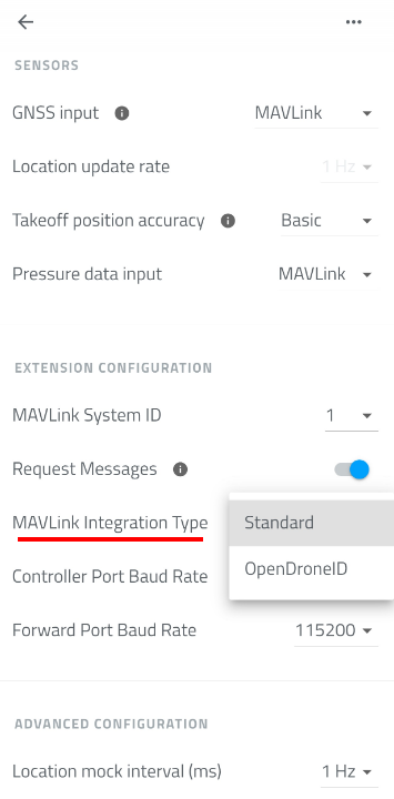
Which compliance modes are available to you depends on the MAVLink Integration Type setting (Configuration screen, Extension Configuration section):
- Standard - the DRI generates the OpenDroneID broadcast internally from its own settings (identification, GNSS/pressure input, etc.). Only the add-on modes can be used with this integration type (EU Add-on and US Add-on), since these represent a Remote ID add-on module rather than a fully integrated system.
- OpenDroneID - the flight controller sends the OpenDroneID data directly to the DRI over MAVLink. All compliance modes are valid with this integration type, including the add-on ones.
Serial Number Override
Every Dronetag DRI ships with its own built-in serial number. For the add-on modes (EU Add-on, US Add-on), this default serial number is used as-is, as long as it is set and in ICAO-compliant format.
For EU C Class and US Standard Remote ID, the drone itself must instead provide its own manufacturer-assigned serial number, which overrides the DRI's default one in the Remote ID broadcast. This value is sent from the flight controller to the DRI in the OPEN_DRONE_ID_BASIC_ID MAVLink message - it is not something you configure in the Toolbox app. See Serial Number Handling in the EU Manufacturer guide or the equivalent section in the US Manufacturer guide for the full requirements, including the recommendation to hardcode it in the flight controller firmware rather than set it from a ground control station.
Because this override is delivered over MAVLink, these two modes require the OpenDroneID MAVLink Integration Type.
Operator ID
Where an Operator ID is required, it is set from the Dronetag Toolbox app rather than from the flight controller. See Set up Identification in the DRI Configuration guide for how to fill it in.
Summary Table
| Compliance Mode | MAVLink Integration Type | Operator ID | Serial Number Override | Operator/Take-off Location | Live Operator Location | Timestamp | Auth (Signature) |
|---|---|---|---|---|---|---|---|
| No Regulation | Standard or OpenDroneID | Not required | Not required | Not required | Not required | Not required | Not required |
| EU Add-on | Standard or OpenDroneID | Required | Not required | Not required | Not required | Not required | Not required |
| EU C Class | OpenDroneID only | Required | Required | Not required | Not required | Not required | Not required |
| US Add-on | Standard or OpenDroneID | Not required | Not required | Required | Not required | Not required | Not required |
| US Standard Remote ID | OpenDroneID only | Not required | Required | Not required | Required | Required | Not required |
| Japan | OpenDroneID only | Not required | Not required | Not required | Not required | Required | Required |
A valid, up-to-date location (position fix), a serial number, and an ICAO-compliant serial number format are required for every mode except No Regulation.
Compliance Modes
No Regulation
No Remote ID compliance checks are enforced. The DRI allows the connected flight controller to arm regardless of identification, location, or messages received.
EU Add-on
Add-on Remote ID mode for the EU. For drones using the Dronetag DRI as a Remote ID add-on module under EU (EASA) rules. See the EU Retrofit guide for full setup.
To arm, the DRI requires:
- A serial number to be set (the DRI's own default is fine)
- The serial number to be in ICAO-compliant format
- A valid Operator ID to be set
- A valid, up-to-date location (position fix)
EU C Class
European C-class compliance (C1–C4). For drones certified into an EU C-class under the Open category. See the EU Manufacturer guide for full setup.
To arm, the DRI requires:
- A serial number to be set
- The serial number to be in ICAO-compliant format
- The serial number to be a manufacturer override (not the DRI's default)
- A valid Operator ID to be set
- A valid, up-to-date location (position fix)
US Add-on
Add-on Remote ID mode for the United States. For drones using the Dronetag DRI as an FAA Remote ID Broadcast Module. See the US Retrofit guide for full setup.
To arm, the DRI requires:
- A serial number to be set (the DRI's own default is fine)
- The serial number to be in ICAO-compliant format
- A valid take-off location for the operator (control station position at take-off)
- A valid, up-to-date location (position fix)
US Standard Remote ID
Full FAA Standard Remote ID compliance. For drones manufactured as FAA-compliant Standard Remote ID aircraft. See the US Manufacturer guide for full setup.
To arm, the DRI requires:
- A serial number to be set
- The serial number to be in ICAO-compliant format
- The serial number to be a manufacturer override
- A valid, live operator location (continuously updated, not just a fixed take-off point)
- A current timestamp in the broadcast data
- A valid, up-to-date location (position fix)
Japan
Remote ID mode for Japan. For drones operated under Japanese drone identification regulations.
To arm, the DRI requires:
- A serial number to be set
- The serial number to be in ICAO-compliant format
- The serial number type to be set to CAA registration ID
- A current timestamp in the broadcast data
- A valid authentication (signature) message to be present
- A valid, up-to-date location (position fix)
DRI GNSS
The Dronetag DRI module can run one of two firmware variants: the standard DRI firmware (used throughout the rest of this Integration Guide) or DRI GNSS. Both run on the exact same physical hardware - switching between them is a firmware choice made from the Dronetag app, and it's fully reversible at any time.
Looking for the Compliance Mode or MAVLink Integration Type settings? Those apply only to standard DRI firmware - see Compliance Mode. DRI GNSS firmware doesn't use MAVLink at all, so neither setting exists there.
When to use DRI GNSS
Standard DRI firmware expects a MAVLink-speaking flight controller (ArduPilot, PX4, etc.) to provide it with position, pressure, and identification data - see the rest of this guide for that setup.
DRI GNSS firmware is for the opposite situation: your flight controller doesn't provide any of that - for example, an FPV/racing build running Betaflight, or any other flight controller that doesn't speak MAVLink. In this mode, the DRI gets its position directly from an external u-blox GNSS receiver connected to its Forward port, instead of from a flight controller.
What DRI GNSS firmware enables
- Uses data from a u-blox GNSS receiver - plug an external u-blox module into the DRI's Forward port, and the DRI reads position from it directly.
- Can upload GNSS assisted data (AGNSS) to the receiver - connect a GNSS configuration tool to the DRI's Controller port to speed up the receiver's time-to-first-fix.
- Forwards data to your flight controller (e.g., Betaflight) - the GNSS receiver's data is relayed out the Controller port, so a flight controller wired there sees the same data it would if the GNSS receiver were connected to it directly.
Wiring
- Forward port → external u-blox GNSS receiver
- Controller port → your flight controller (receives the relayed GNSS data), and/or a laptop/GNSS configuration tool for AGNSS upload
Switching between DRI and DRI GNSS
Switching is done from the Dronetag app and performs a firmware update on the device. You can switch back to standard DRI firmware the same way, at any time - nothing is one-way.
Switching to DRI GNSS
The Dronetag app shows the following when switching a standard DRI to the GNSS variant:
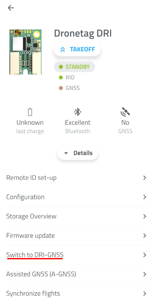
Switch to Dronetag DRI GNSS
Your Dronetag DRI can be switched to Dronetag DRI-GNSS variant. Switch between the variants to adapt to your specific needs. Both variants provide the Remote ID functionality in different ways.
Switching to DRI-GNSS variant will enable the following features:
- Uses data from a Ublox GNSS receiver.
- Can upload GNSS assisted data to the receiver.
- Forwards data to your flight controller (e.g., Betaflight).
Switching will perform a special firmware update on your device. The switch is reversible by visiting this screen again.
Switching back to standard DRI
Switch to Dronetag DRI Module
Your Dronetag DRI-GNSS can be switched to Dronetag DRI variant. Switch between the variants to adapt to your specific needs. Both variants provide the Remote ID functionality in different ways.
Switching to original DRI variant will enable the following features:
- Integrates with Mavlink flight controllers.
- Uses data from the flight controller.
Switching will perform a special firmware update on your device. The switch is reversible by visiting this screen again.
Antennas
Preapproved Antennas
The following is a list of certified external antennas compatible with the Dronetag DRI module. These antennas meet CE requirements and are suitable for integrators looking for compliant hardware.
| Antenna Code / Name | Manufacturer | Sensitivity (Gain) | Dimensions (mm) | Cable Length |
|---|---|---|---|---|
| FXP75.07.0045B | Taoglas | +2.5 dBi | 5.9 x 4.1 x 0.24 | 45 mm |
| FXP74.07.0100A | Taoglas | +4.0 dBi | 47.0 x 7.0 x 0.1 | 10 mm |
| PC17.07.0070A | Taoglas | +1.0 dBi | 24.0 x 11.0 x 0.8 | 70 mm |
| FXP72.07.0053A | Taoglas | +5.0 dBi | 31.0 x 31.0 x 0.1 | 53 mm |
For full specifications and compliance details, refer to the original PDF: Pre-approved Antennas (SharePoint)
Diagrams
This page provides visual and technical references for the DRI module. In the first part, you will find diagrams illustrating the physical layout and position of key components on the module. The second part contains detailed specifications of the connector pinouts and supported communication protocols, ensuring correct integration with the flight controller and other onboard systems.
Highlight diagrams
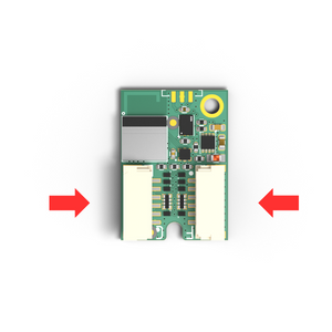
Flight Controller Port
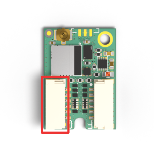 | Port designed to connect the flight controller unit. For different integration wiring diagrams see section Integration |
Flight Forward Port
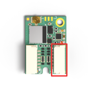 | Port designed to forward communication to the flight controller unit. To configure forwarding please see Configuration. |
LED Indicator
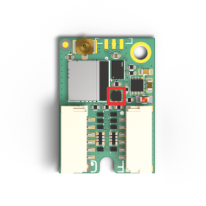 | RGB LED indication. For details please go to section LED Indications. |
Antenna U.FL Connector
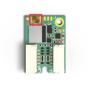 | U.FL series connector for external Bluetooth antenna. |
M2 Mounting Holes
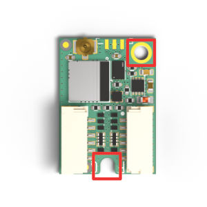 | Standardized M2 Mounting Hole. |
Wiring Diagrams
Operating voltage: 3.5V - 17V
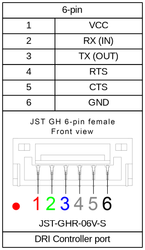
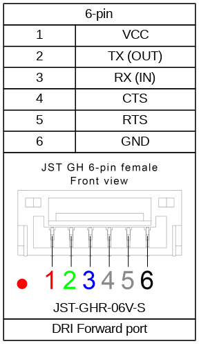
Flight controller port (Port C)
Default settings:
| |
Forwarding port (Port F)
Default settings:
| |
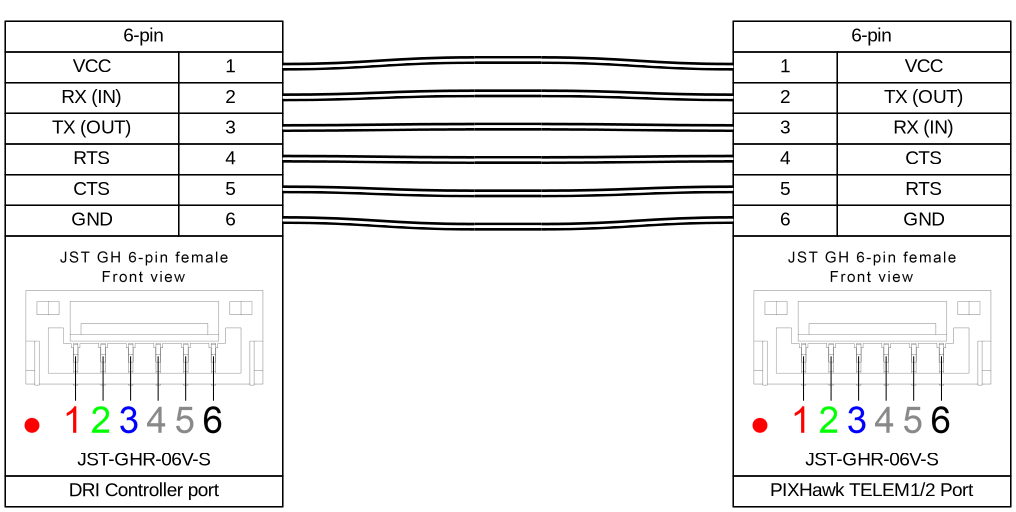
Pixhawk connection
Connect DRI to the PixHawk TELEM port according to the wiring diagram below.
DRI Configuration
This guide explains how to configure your Dronetag DRI using a mobile application. It applies to all:
- Integration in EU
- Retrofit Integration in US
- Standard Remote ID for Manufacturers in US
Requirements
Before starting, make sure:
- You have a compatible flight controller (e.g., Holybro Pix32v5, Cube Orange, etc.)
- You’ve already flashed the correct firmware:
- Standard ArduPilot or PX4 for retrofit
- ArduPilot with OpenDroneID support for full integration; Note: PX4 currently does not support OpenDroneID
- How to create and flash firmware with OpenDroneID support is described on the page Unique firmware for Flight Controller
- You’re using a supported mobile app:
Step-by-Step Guide
Power up your Drone
Connect the battery to your drone to power up the flight controller and the Dronetag DRI for configuration.
Select your Dronetag DRI
Open your Dronetag Toolbox application. On the title page, you should see active DRI devices in your proximity.
Go to Identification
In the menu, select the "Identification" option.
Set up Identification
The DRI device, and thus your drone identification, is configured on this screen.
- Integration in EU
- Integration in US
Select the EU as the Remote ID setup.
Fill in the UAS Operator ID issued by your country's CAA.
Then select to save the identification.Select the United States as the Remote ID setup.
This will set the DRI device to use its serial number as the identification.
Then select to save the identification.Go to Configuration
As the next step, go to the Configuration screen.
Set up the DRI
- Integration in EU/Retrofit Integration in USA
- Standard Remote ID for Manufacturers in USA
Check the settings of the highlighted items:
- Enable MAVLink flight start - True
- GNSS Input - MAVLink
- Pressure data input - MAVLink
- MAVLink Integration Type - Standard
- Controller Port Baud Rate - 115200
Check the settings of the highlighted items:
- Enable MAVLink flight start - True
- GNSS Input - MAVLink
- Pressure data input - MAVLink
- MAVLink Integration Type - OpenDroneID
- Controller Port Baud Rate - 115200
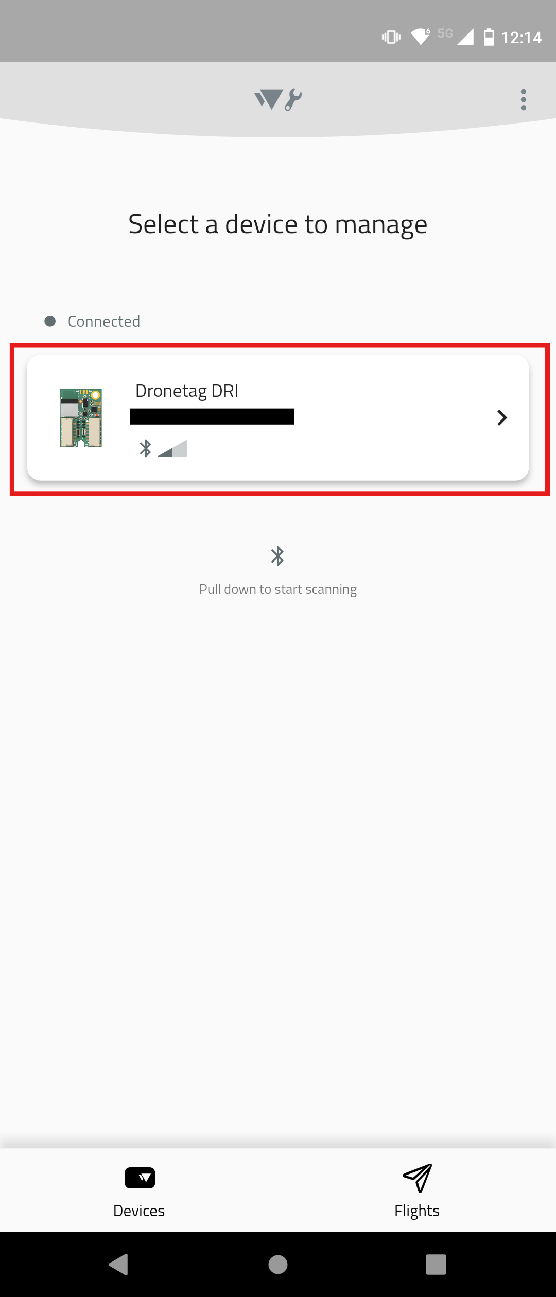
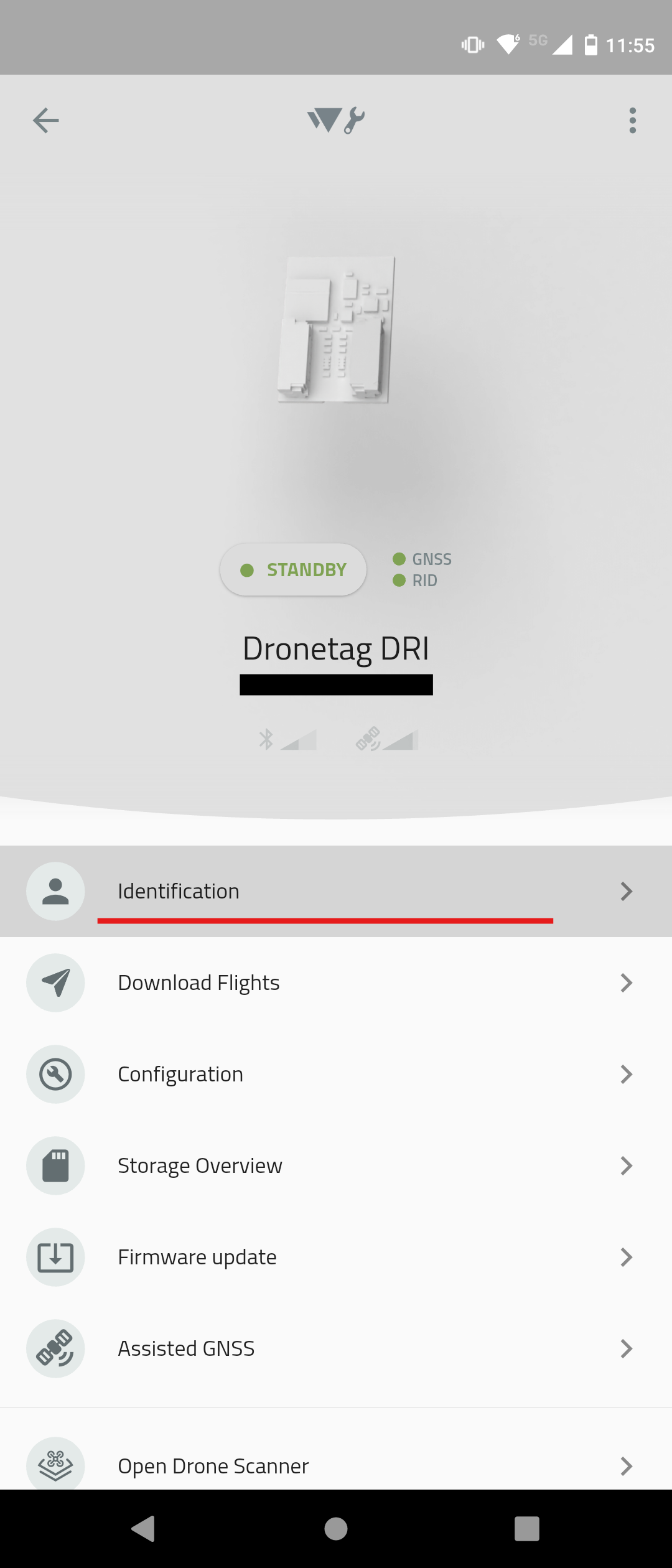
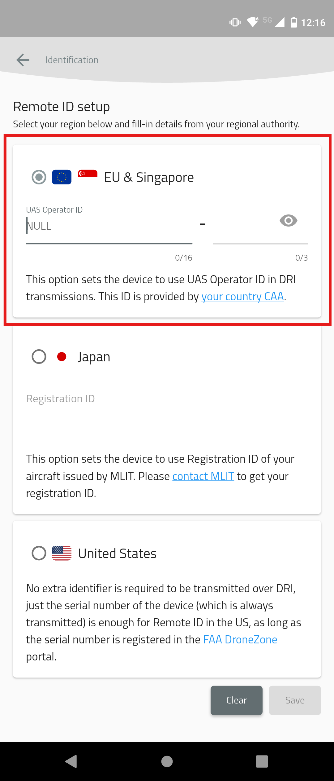
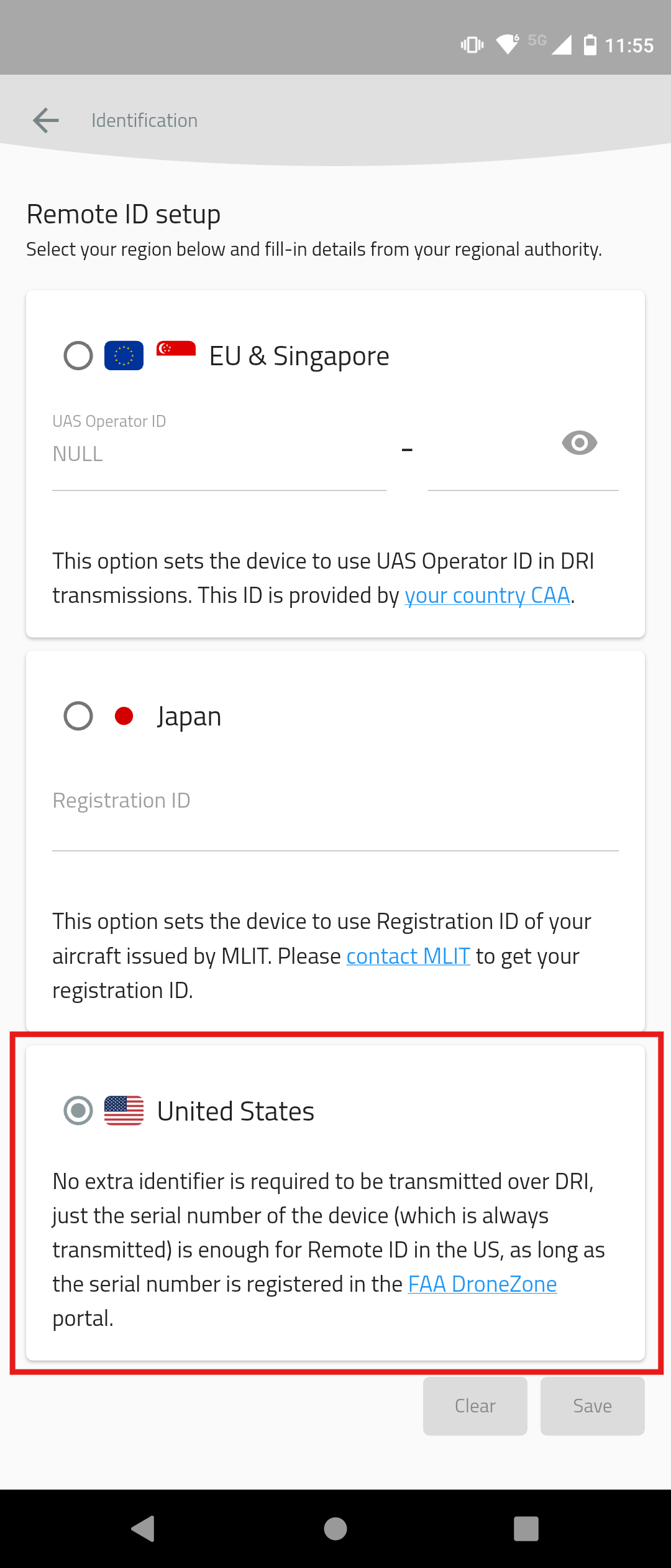
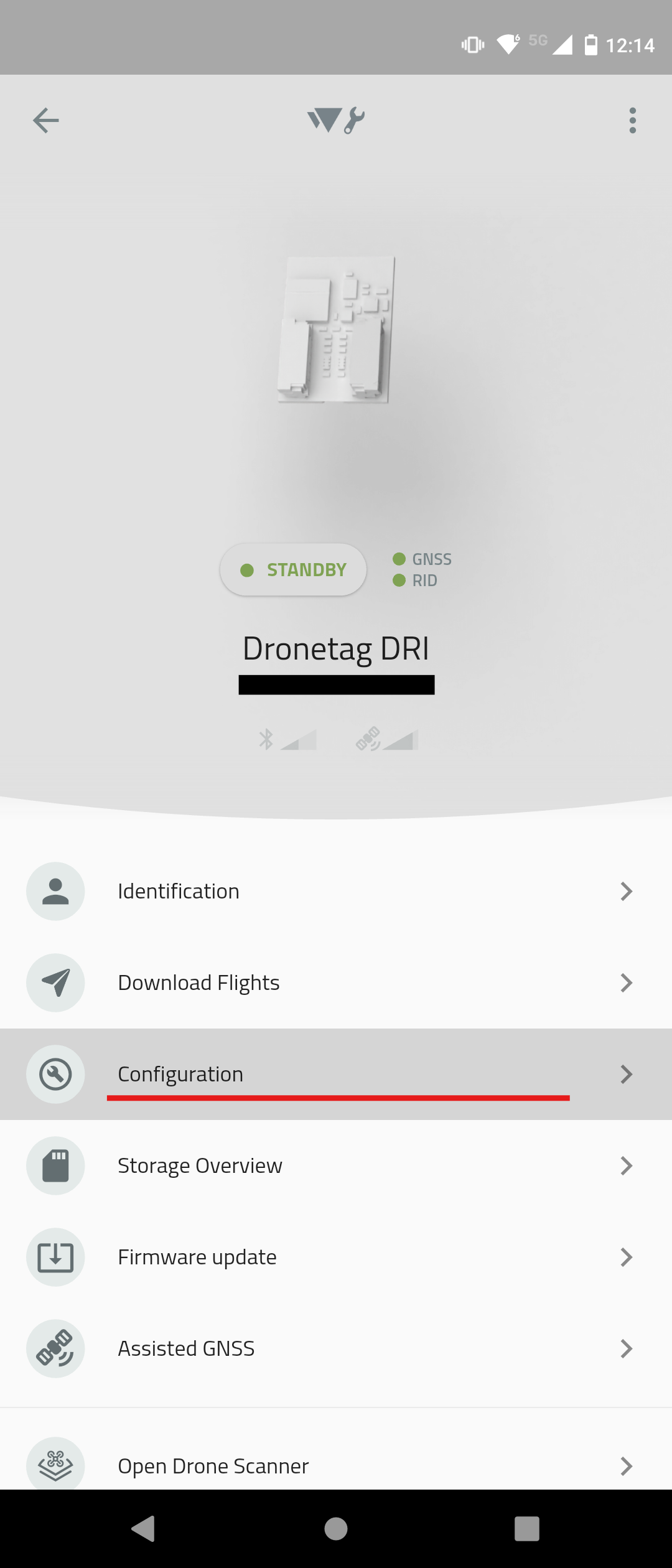
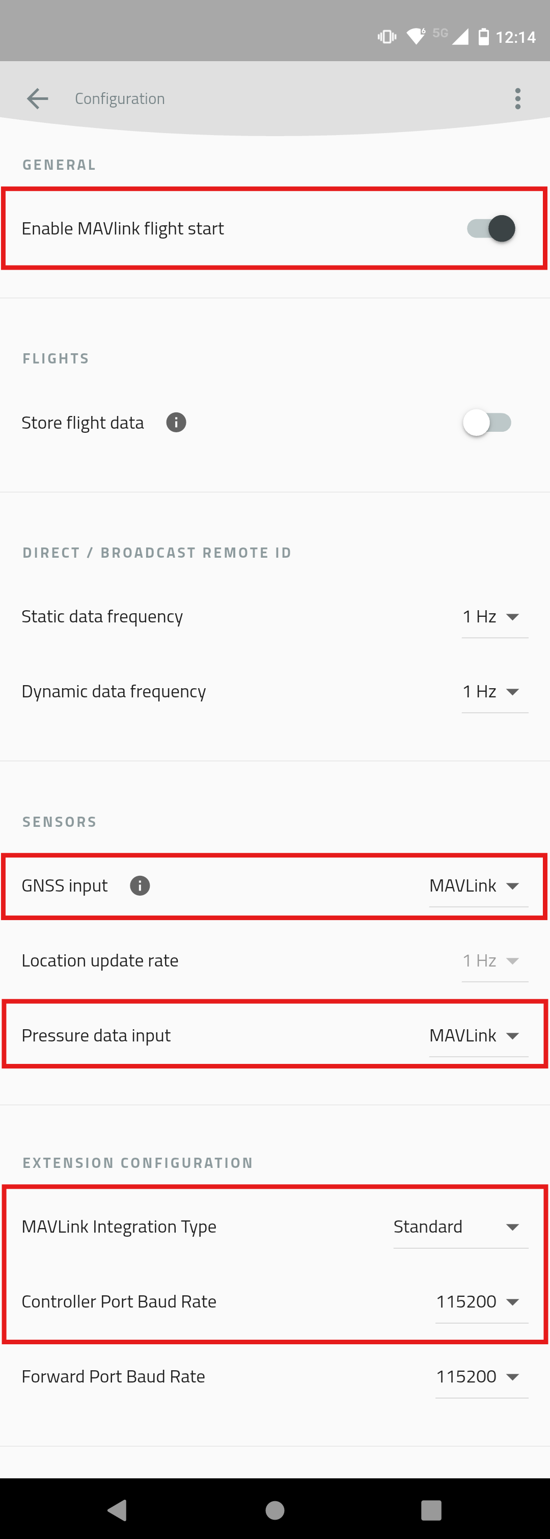

Next Steps
For Remote ID compliance in the EU, continue with Connect the Flight Controller to PC in the Integration in EU guide.
For Remote ID compliance in the US through retrofit using a Dronetag DRI module, continue with Connect the Flight Controller to PC in the Retrofit Integration in USA guide.
For Standard Drone ID compliance in the US for manufacturers, continue with Connect the Flight Controller to PC in the Standard Remote ID for Manufacturers in USA guide.
Flight Controller Configuration
This guide explains how to configure your flight controller to work with the Dronetag DRI module. It applies to all:
- Integration in EU
- Retrofit Integration in US
- Standard Remote ID for Manufacturers in US
Requirements
Before starting, make sure:
- You have a compatible flight controller (e.g., Holybro Pix32v5, Cube Orange, etc.)
- You’ve already flashed the correct firmware:
- Standard ArduPilot or PX4 for retrofit
- ArduPilot with OpenDroneID support for full integration; Note: PX4 currently does not support OpenDroneID
- How to create and flash firmware with OpenDroneID support is described on the page Unique firmware for Flight Controller
- You know which flight controller's serial/telemetry port is connected to Dronetag DRI (Port C)
- You’re using a supported configuration tool:
- QGroundControl (ArduPilot or PX4)
- Mission Planner (ArduPilot)
We will use the Holybro Pix32v5 flight controller in this guide.
Step-by-Step Guide
Choose the firmware running on your flight controller:
- ArduPilot
- PX4
Choose the configuration tool:
- QGroundControl
- Mission Planner
Connect to the Drone
Connecting your flight controller to your PC via USB is the fastest and most reliable method. QGroundControl should automatically connect to the most common devices. If your flight controller connects automatically, skip to Open the Vehicle Configuration. For the official guide to setting up the connection, follow the QGroundControl documentation.
SiK TelemetryConnection using a SiK telemetry radio does not require a physical connection between the flight controller and PC, but it is much slower to work with than the USB method. How to use the Holybro SiK radio is described on the page Holybro SiK Radio V3 documentation.
SiK Telemetry warningIf you decide to connect a SiK Telemetry through the Port-Forwarding feature of the DRI, do not connect RTS/CTS lines between the DRI and the SiK radio.
Manually Create the Link Profile
- Open the QGroundControl menu by clicking on the QGroundControl icon in the top left corner and select Application Settings.
- In the Application Settings window, select Comm Links and then select the Add New Link option to open the Add New Link form.
- In the Add New Link form, enter the name of the profile, select the flight controller serial port, and set the baud rate to 115200.
- Return to the main window.
Connect Using Prepared Link Profile
- In the main window, click on "Click to manually connect" and select your link profile. If QGroundControl can't connect to the flight controller, please check the correctness of the link profile created during step Manually Create the Link Profile.
Open the Vehicle Configuration
- Open the QGroundControl menu by clicking on the QGroundControl icon in the top left corner and select Vehicle Configuration.
Configure Parameters
In the Vehicle Configuration window, select Parameters in the menu and then use the parameter search.
Search for the following parameters and set the correct values, where 'x' denotes the serial port number the DRI is connected to:
SERIALx_PROTOCOL = MAVLink2 protocolSERIALx_BAUD = 115200 baudBRD_SERx_RTSCTS = Disabled
If you want to enable OpenDroneID support, then set the additional parameters:
DID_ENABLE = Enabled(Enable OpenDroneID support)DID_MAVPORT = x(Set the port to which the DRI is connected)
infoTo set up your flight controller to support OpenDroneID, the flight controller must run unique firmware. The guide Standard Remote ID for Manufacturers in USA describes this integration process.
Validate MAVLink Communication
After configuration of the parameters, the DRI should communicate with the flight controller. We can check if the correct messages are received by the flight controller.
To view MAVLink communication statistics, switch to Analyze Tools - MAVLink Inspector. There is a list of received MAVLink messages and the frequency of their reception.
Check if there is the following message from ID 263:
MAVLINK_MSG_ID_HEARTBEATIt should look like the image:
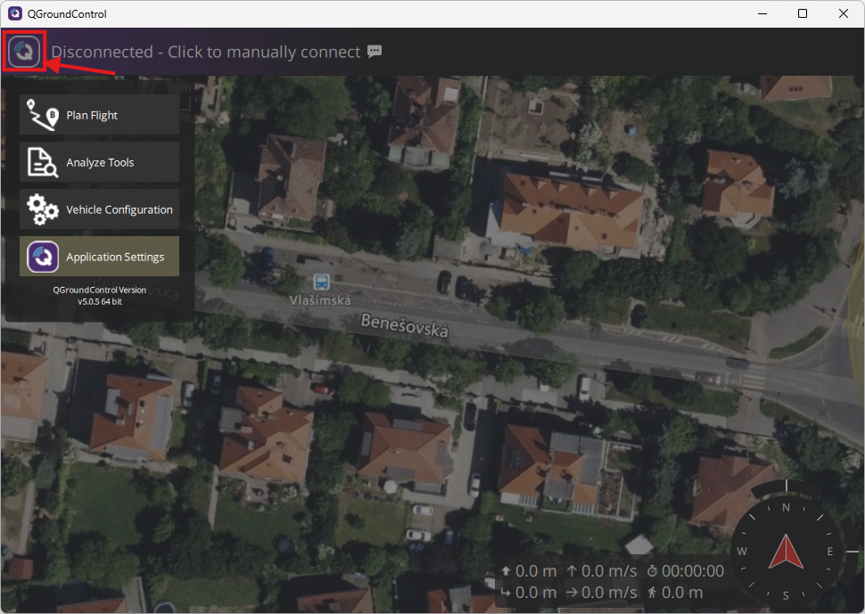
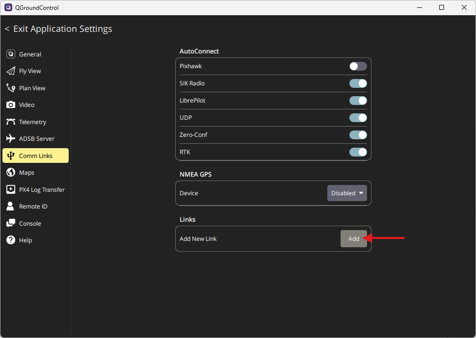
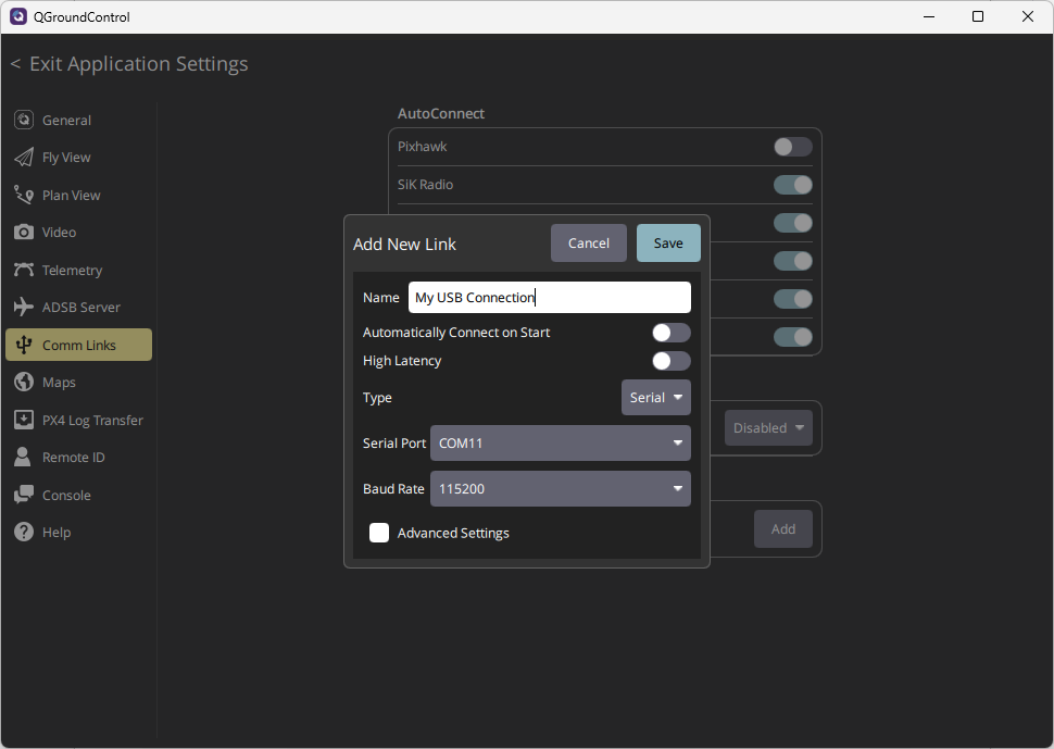
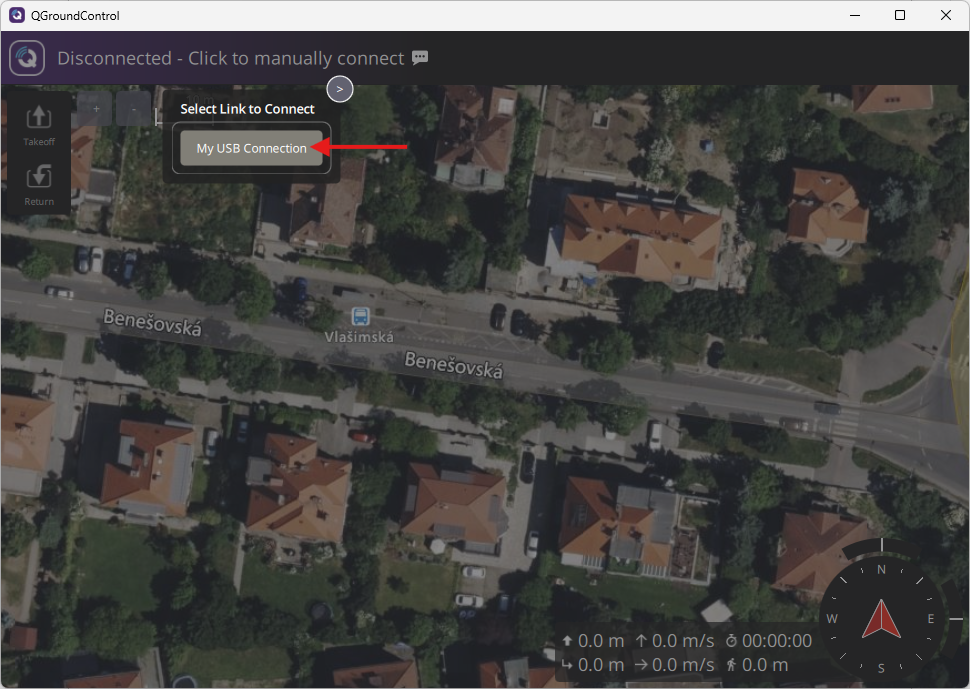
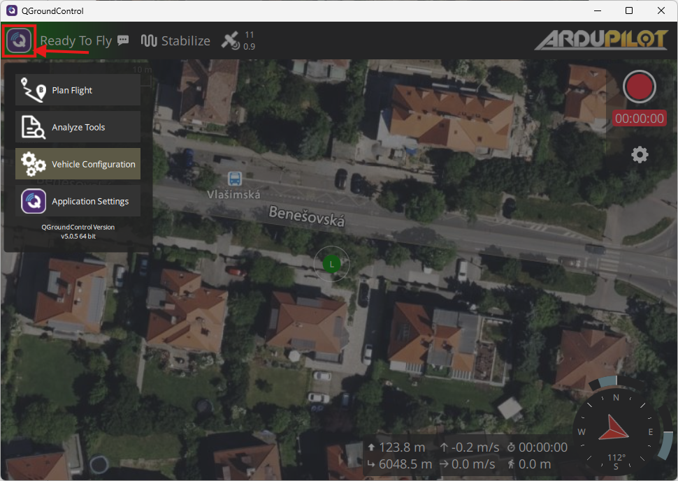
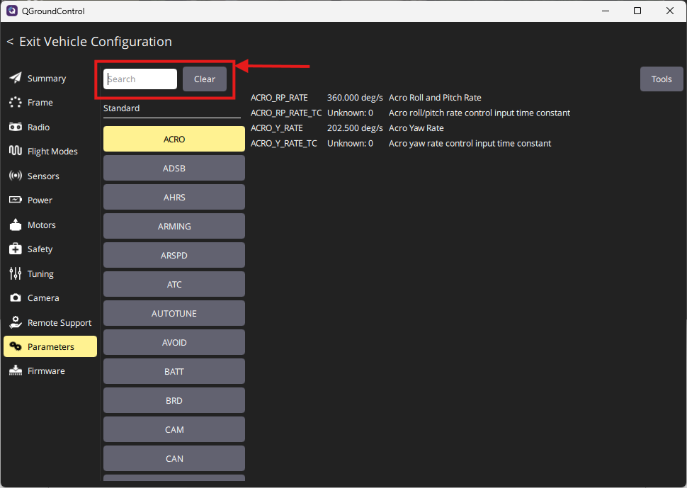
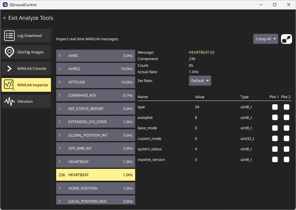
Connect to the Drone
Connect your flight controller to your PC via USB. This is the fastest and most reliable method.
SiK TelemetryConnection using a SiK telemetry radio does not require a physical connection between the flight controller and PC, but it is much slower to work with than the USB method. How to use the Holybro SiK radio is described on the page Holybro SiK Radio V3 documentation.
SiK Telemetry warningIf you decide to connect a SiK Telemetry through the Port-Forwarding feature of the DRI, do not connect RTS/CTS lines between the DRI and the SiK radio.
Connect Using Serial Port
In Mission Planner, configure the connection port and baud rate in the upper right corner of the Mission Planner window. The USB connection baud rate should be 115200. Then press the Connect button. If you need help setting up the connection, follow the ArduPilot with Mission Planner documentation.
Open Config Window
Configure Parameters
In the Config window, select Full Parameter List in the menu and then use the parameter search.
Search for the following parameters and set the correct values, where 'x' denotes the serial port number the DRI is connected to:
SERIALx_PROTOCOL = 2(MAVLink2 protocol)SERIALx_BAUD = 115(115200 baud rate)BRD_SERx_RTSCTS = 0(Disabled flow control)
If you want to enable OpenDroneID support, then set the additional parameters:
DID_ENABLE = 1(Enable OpenDroneID support)DID_MAVPORT = x(Set the port to which the DRI is connected)
infoTo set up your flight controller to support OpenDroneID, the flight controller must run unique firmware. The guide Standard Remote ID for Manufacturers in USA describes this integration process.
Validate MAVLink Communication
After configuring the parameters, the DRI should communicate with the flight controller. You can check whether the correct messages are being received by the flight controller.
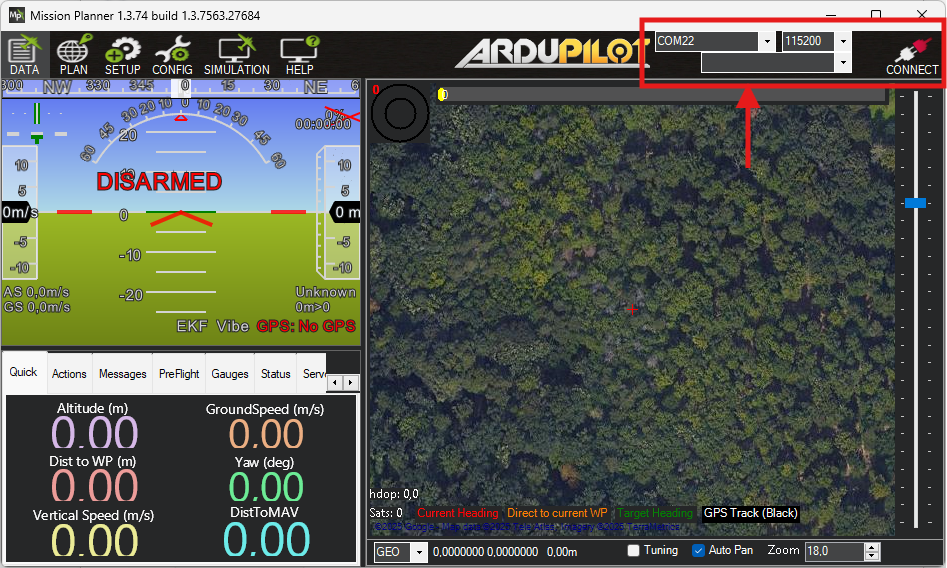
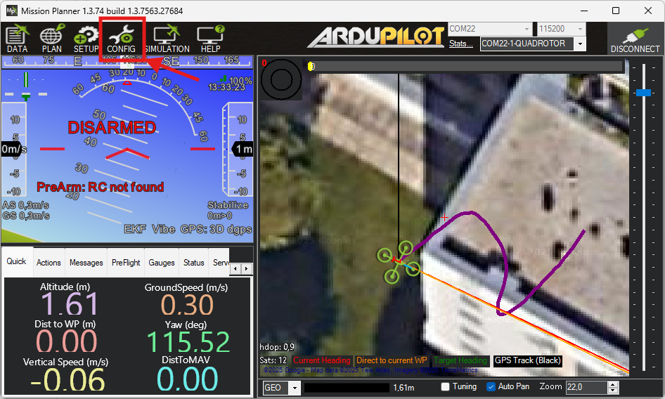
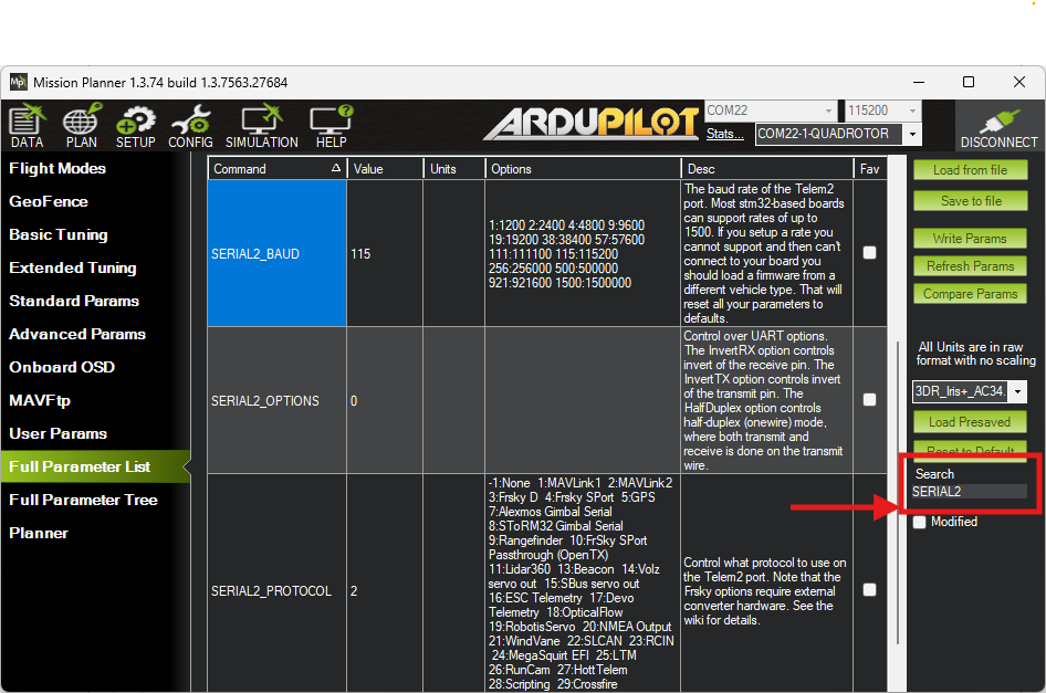
Connection Method
- USB Cable
- SiK Telemetry
PX4 may not show a heartbeat over USB. Use a telemetry connection with forwarding enabled.
Connect using a telemetry radio and enable MAVLink forwarding.
Configuration Steps
Use QGroundControl to set the following parameters:
MAV_x_CONFIG = 102
MAV_x_FLOW_CTRL = 2
MAV_x_FORWARD = 1
MAV_x_MODE = 0
MAV_x_RADIO_CTL = 1
MAV_x_RATE = 1200
SER_TELx_BAUD = 115200
This setup enables basic MAVLink communication for Remote ID broadcast.
PX4 currently does not support full OpenDroneID integration. For details on current capabilities and supported hardware, refer to the PX4 Remote ID documentation.
Next Steps
For Remote ID compliance in the EU, continue with Confirm LED Status after FC Configuration in the Integration in EU guide.
For Remote ID compliance in the US through retrofit using a Dronetag DRI module, continue with Confirm LED Status after FC Configuration in the Retrofit Integration in USA guide.
For Standard Drone ID compliance in the US for manufacturers, continue with Configure the Ground Control Station in the Standard Remote ID for Manufacturers in USA guide.
Custom Flight Controller Guide
This page is intended for developers building custom firmware for flight controllers that integrate the Dronetag DRI module.
It explains what must be respected, implemented, and tested to achieve Remote ID compliance in both the USA (FAA Part 89) and the EU (Regulation 2019/945).
Purpose
- Define the MAVLink messages required for DRI integration.
- Show how to use the MAVLink Transport Sender as a reference generator.
- Clarify which parameters must be hardcoded in firmware and which can remain configurable.
- Provide guidance on testing and verification using available tools.
Minimal Setup
To begin development with the Custom Firmware Guide, you only need the following:
-
Dronetag DRI module
(recommended: U.FL antenna variant) -
Compatible antenna for the U.FL variant
A small testing antenna is included with the Dronetag DRI.
We recommend choosing a pre‑approved antenna from our approved list. -
Smartphone supporting BLE 5.0
Used for broadcast verification. -
USB to Serial Adapter with compatible cable
Dronetag DRI and a Pixhawk compatible flight controller motherboard telemetry/serial port usually uses a JST‑GH connector (Pixhawk standard, typically 6‑pin).
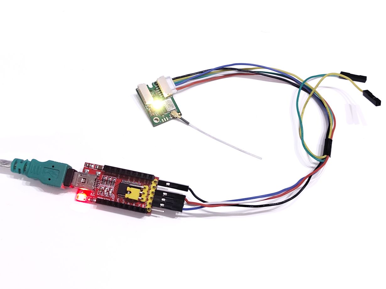
Minimal Setup Diagrams
The following diagrams illustrate two typical ways to start development with the minimal setup:
-
Simulated Flight Controller on PC
Example connection using a USB–Serial adapter. This setup allows you to simulate the Flight Controller directly from your computer using MAVLink Transport Sender and verify communication with the Dronetag DRI.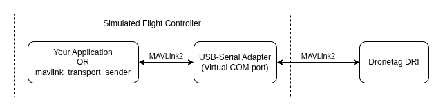
-
Real Flight Controller
Example connection where the Dronetag DRI is connected to the Flight Controller’s serial interface (UART). This setup closely resembles the final deployment scenario.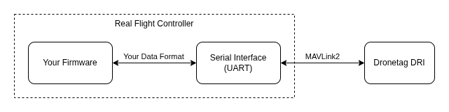
This minimal setup is a good starting point for development and testing, as it already mirrors the final use case where the DRI communicates with the Flight Controller over a serial link.
Required MAVLink Messages
The flight controller must publish the following messages to the DRI:
- MAVLINK_MSG_ID_HEARTBEAT – system status.
- MAVLINK_MSG_ID_GPS_RAW_INT / MAVLINK_MSG_ID_GLOBAL_POSITION_INT – GNSS position.
- MAVLINK_MSG_ID_SCALED_PRESSURE / MAVLINK_MSG_ID_ALTITUDE – barometric altitude.
- MAVLINK_MSG_ID_SYSTEM_TIME – time reference.
- OpenDroneID set:
- OPEN_DRONE_ID_BASIC_ID,
- OPEN_DRONE_ID_LOCATION,
- OPEN_DRONE_ID_SYSTEM,
- OPEN_DRONE_ID_OPERATOR_ID,
- OPEN_DRONE_ID_ARM_STATUS.
These messages form the minimum set for Remote ID compliance.
Reference Implementation
We provide MAVLink Transport Sender as a reference generator:
- Publishes all required MAVLink and OpenDroneID messages.
- Demonstrates how values change with flight state (GNSS fix, operator ID, arming).
- Can be used as a functional example to replicate message generation in firmware.
- Developers may re‑implement the same logic using the official MAVLink library or custom serialization.
Hardcoded vs. Configurable Parameters
USA (FAA Part 89, ANSI/CTA‑2063‑A, ASTM F3411)
- Hardcoded in firmware:
- Remote ID serial number (OPEN_DRONE_ID_BASIC_ID).
- Must follow ICAO/ANSI/CTA‑2063‑A format.
- Each unit has a unique serial, registered in FAA DroneZone.
- Configurable:
- Operator location (OPEN_DRONE_ID_SYSTEM), sent from GCS with GNSS.
- Flight controller relays last known operator location if GCS link is lost.
EU (Regulation 2019/945, EN 4709‑002)
- Hardcoded in firmware:
- UAS serial number (OPEN_DRONE_ID_BASIC_ID).
- Must follow ICAO/ANSI/CTA‑2063‑A format.
- Stored in tamper‑resistant memory, not editable by user.
- Configurable:
- Operator ID (OPEN_DRONE_ID_OPERATOR_ID).
- Must be user‑settable via GCS or configuration interface.
- Failsafe:
- Drone must refuse takeoff if DRI or GNSS is not functional.
- Broadcast must continue even if GCS link is lost.
Testing and Verification
To confirm correct implementation:
- Use the Dronetag DroneScanner app on a BLE 5.0-capable device:
- Check that:
- Serial number is present and matches firmware.
- Operator ID is correctly transmitted (EU).
- Operator location is correctly relayed (USA).
- Location and altitude update smoothly.
- ARM_STATUS prevents takeoff if DRI or GNSS is missing.
- Optionally use BLE sniffing tools (e.g. nRF Sniffer) for deeper analysis.
Summary
By respecting the required MAVLink messages, hardcoding mandatory serial numbers, and exposing Operator ID or operator location as configurable where required, integrators can ensure their custom firmware works seamlessly with Dronetag DRI and meets Remote ID compliance requirements in both the USA and EU.
For legal references, see:
- FAA 14 CFR Part 89 and FAA AC 89‑2
- EU Regulation 2019/945 and harmonized standard EN 4709‑002
Source pages
Every chapter of this document is a page of the Dronetag help site. Use these addresses to reach the latest version.
- 1Retrofit Integration in the EUhelp.dronetag.cz/dronetag-dri/integration/eu-retrofit
- 2Retrofit Integration in the USAhelp.dronetag.cz/dronetag-dri/integration/usa-retrofit
- 3C‑class for Manufacturers in the EUhelp.dronetag.cz/dronetag-dri/integration/eu-manufacturer
- 4Standard Remote ID for Manufacturers in the USAhelp.dronetag.cz/dronetag-dri/integration/usa-manufacturer
- 5Compliance Modehelp.dronetag.cz/dronetag-dri/integration/compliance-mode
- 6DRI GNSShelp.dronetag.cz/dronetag-dri/integration/dri-gnss
- 7Antennashelp.dronetag.cz/dronetag-dri/integration/antennas
- 8Diagramshelp.dronetag.cz/dronetag-dri/integration/diagrams
- 9DRI Configurationhelp.dronetag.cz/dronetag-dri/integration/dri-configuration
- 10Flight Controller Configurationhelp.dronetag.cz/dronetag-dri/integration/fc-setup
- 11Custom Flight Controller Guidehelp.dronetag.cz/dronetag-dri/integration/custom-firmware