
Installation Guide
- Document
- Dronetag Scout — Installation Guide
- Chapters
- 8
- Source
- help.dronetag.cz/cs/print/dronetag-scout/installation-guide
What is in the Box
At Dronetag, we strive to deliver the most functional and reliable solutions for your Remote ID needs.
Each Scout package is carefully assembled to ensure you have everything required for a smooth and efficient setup.
- Baseline
- 2x Omni and 1x 90° Directional
- 2x Omni and 2x 90° Directional
- 2x Omni and 3x 90° Directional
- 1x Omni and 4x 90° Directional
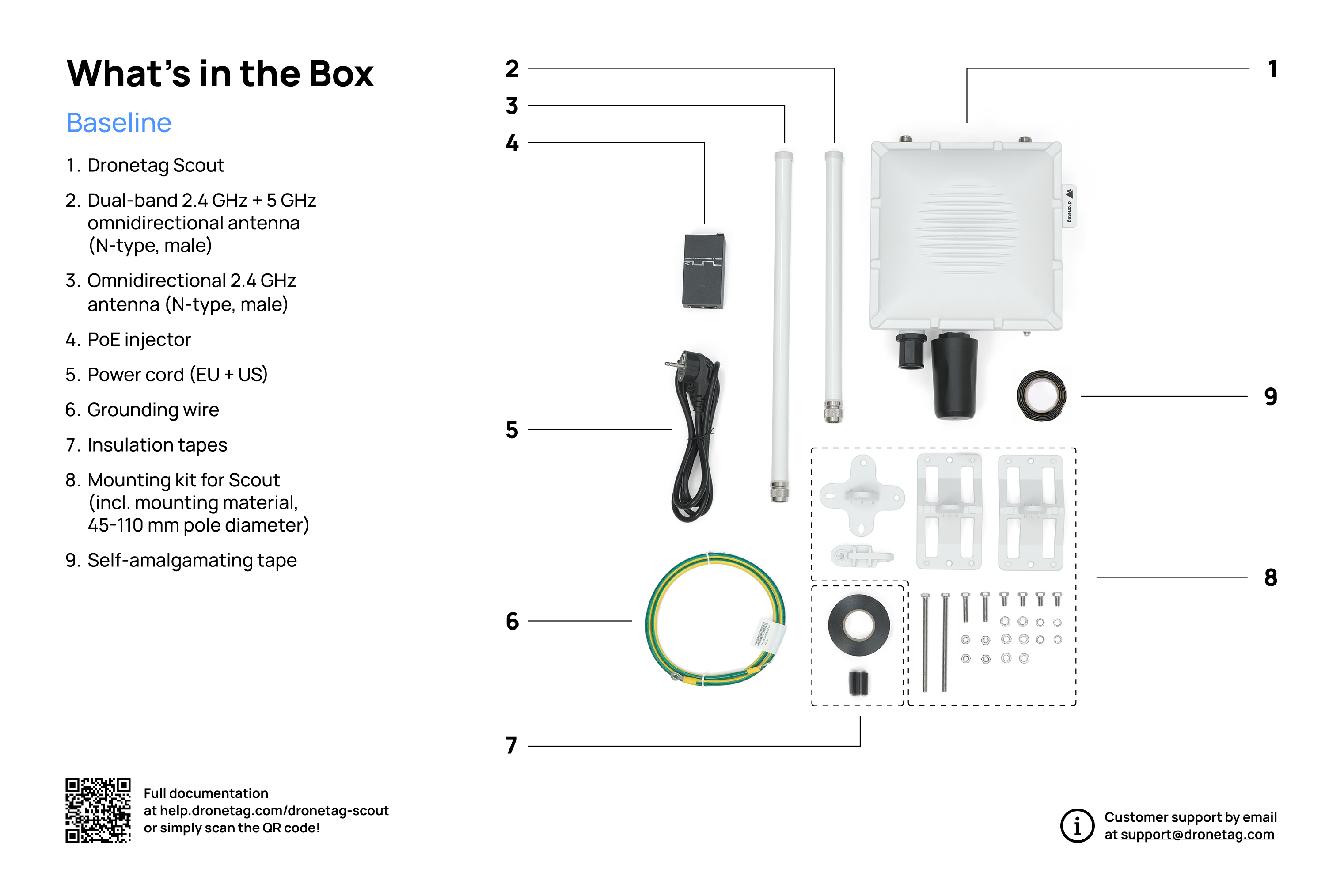
Scout Baseline
Once you receive your Scout device with its basic configuration, you should find everything neatly packed in the delivery box. Here’s what to expect when unboxing your new Scout system:
This image illustrates the standard contents included in the Scout baseline package.
3D Model
- Scout Baseline – compact, omnidirectional setup for general coverage
👉 View 3D model
The Scout package comes in a sturdy box with the following dimensions:
450 mm x 300 mm x 150 mm / 17.7" x 11.8" x 5.9"
This compact size ensures the contents are well-protected during transport while still being easy to handle.
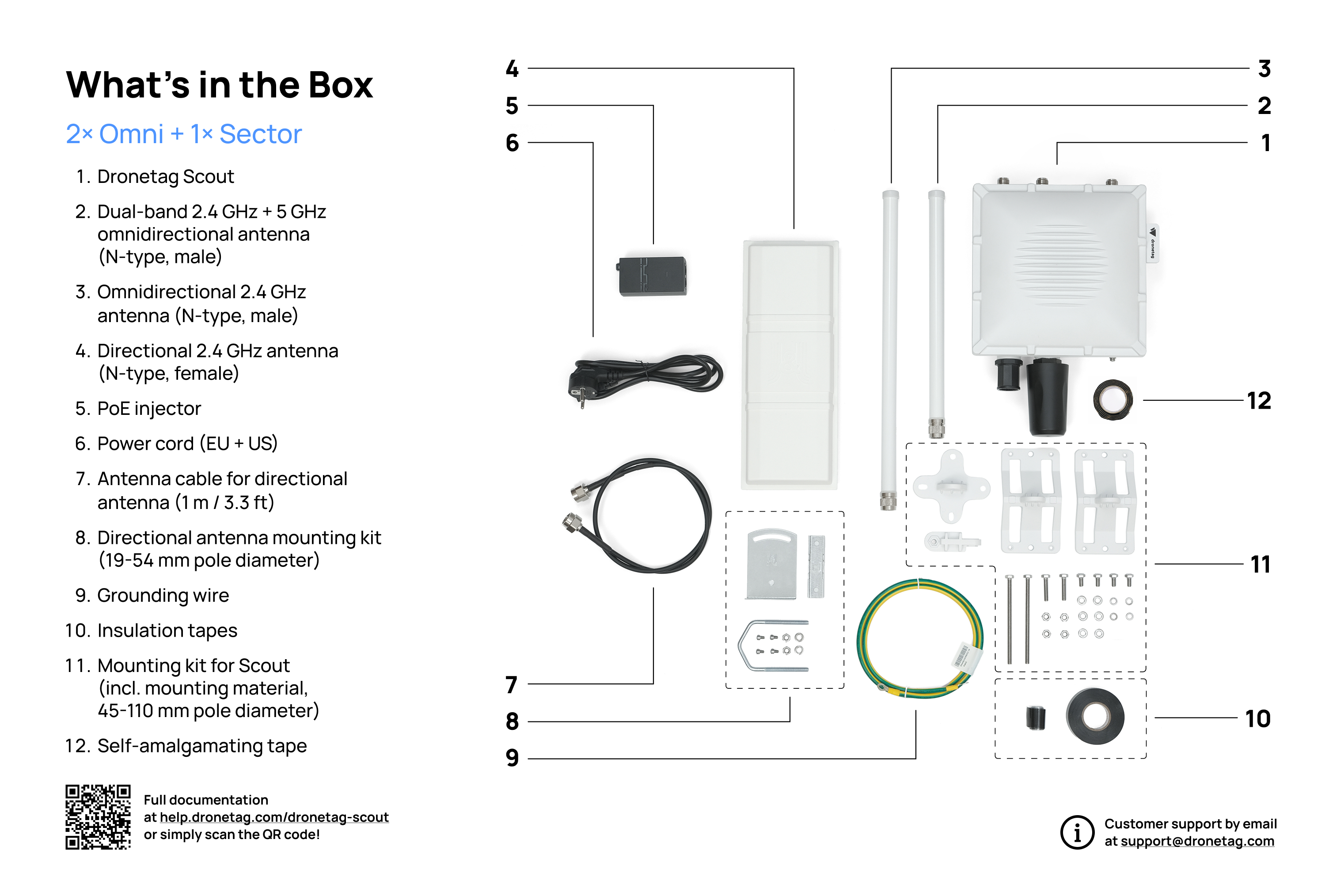
Scout with 2x Omnidirectional + 1x 90° Directional Antennas
Once you receive your Scout device with the directional antennas configuration, you’ll find everything neatly packed in the delivery box. Here’s what to expect when unboxing your new Scout system.
This image illustrates the standard contents included in the package of Scout with directional antennas.
The Scout with directional antennas package comes in a box with adjustable height and has the following maximal dimensions:
450 mm x 350 mm x 250 mm / 17.7" x 13.8" x 9.8"
The actual height depends on the specific Scout configuration. This size ensures the contents are well-protected during transport while still being easy to handle.
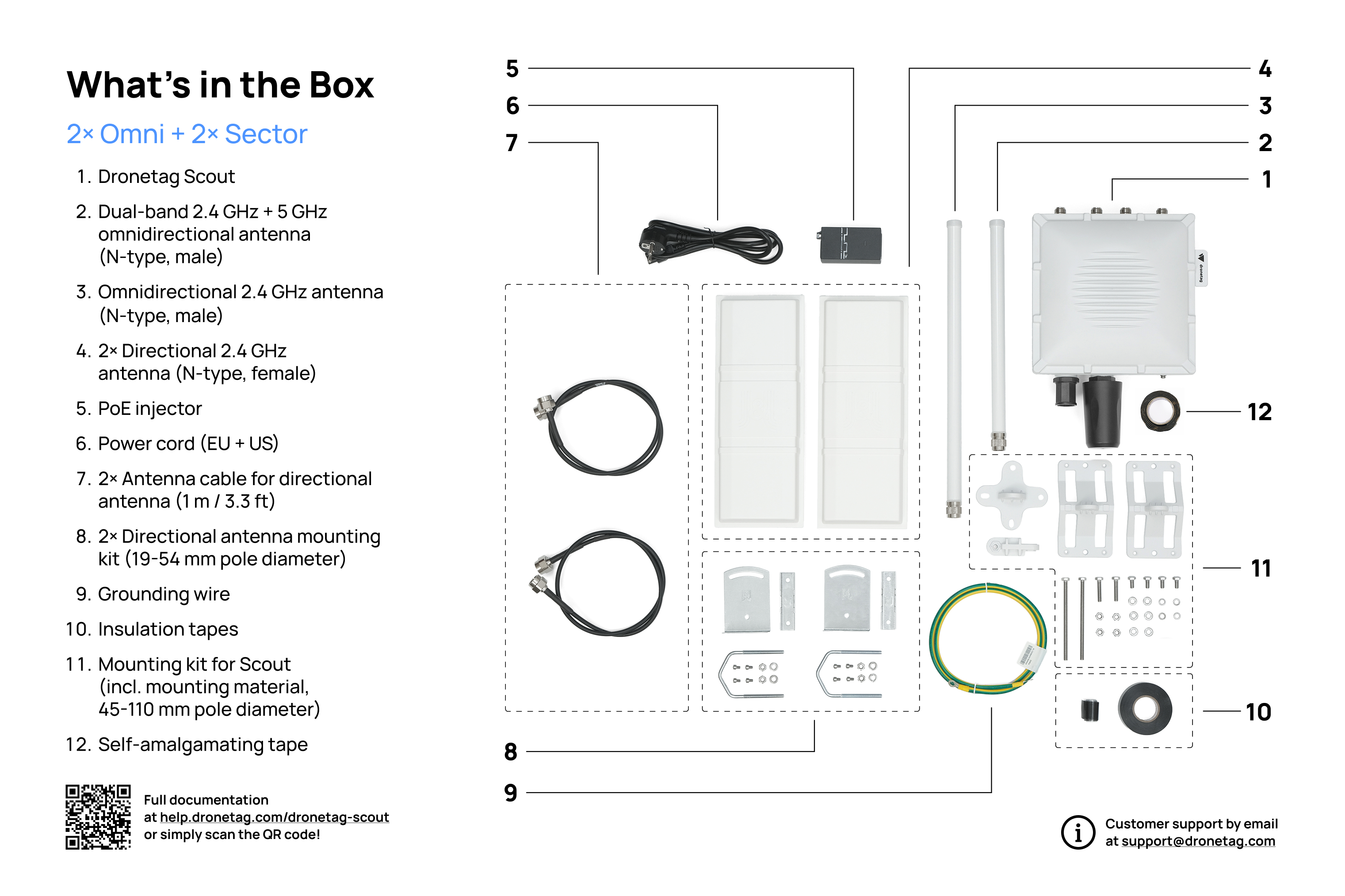
Scout with 2x Omnidirectional + 2x 90° Directional Antennas
Once you receive your Scout device with the directional antennas configuration, you’ll find everything neatly packed in the delivery box. Here’s what to expect when unboxing your new Scout system.
This image illustrates the standard contents included in the package of Scout with directional antennas.
3D Model
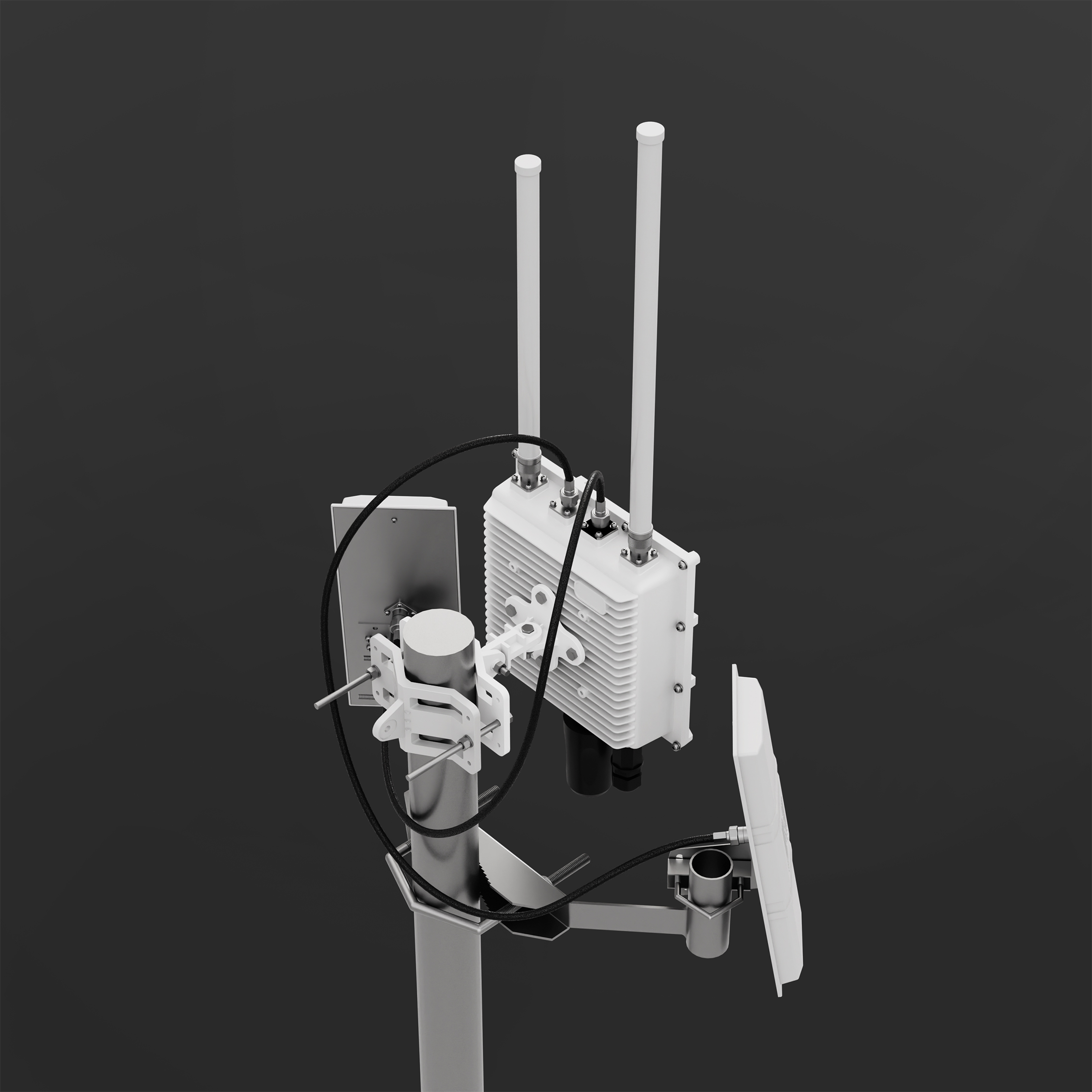
The Scout with directional antennas package comes in a box with adjustable height and has the following maximal dimensions:
450 mm x 350 mm x 250 mm / 17.7" x 13.8" x 9.8"
The actual height depends on the specific Scout configuration. This size ensures the contents are well-protected during transport while still being easy to handle.
Scout with 2x Omnidirectional + 3x 90° Directional Antennas
Once you receive your Scout device with the directional antennas configuration, you’ll find everything neatly packed in the delivery box. Here’s what to expect when unboxing your new Scout system.
This image illustrates the standard contents included in the package of Scout with directional antennas.
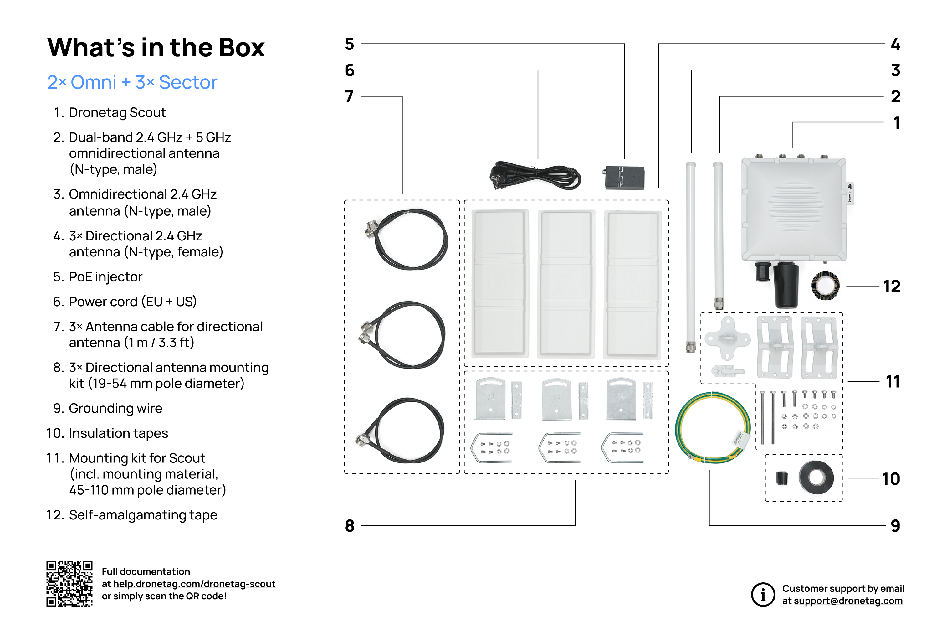
The Scout with directional antennas package comes in a box with adjustable height and has the following maximal dimensions:
450 mm x 350 mm x 250 mm / 17.7" x 13.8" x 9.8"
The actual height depends on the specific Scout configuration. This size ensures the contents are well-protected during transport while still being easy to handle.
Scout with 1x Omnidirectional + 4x 90° Directional Antennas
Once you receive your Scout device with the directional antennas configuration, you’ll find everything neatly packed in the delivery box. Here’s what to expect when unboxing your new Scout system.
This image illustrates the standard contents included in the package of Scout with directional antennas.
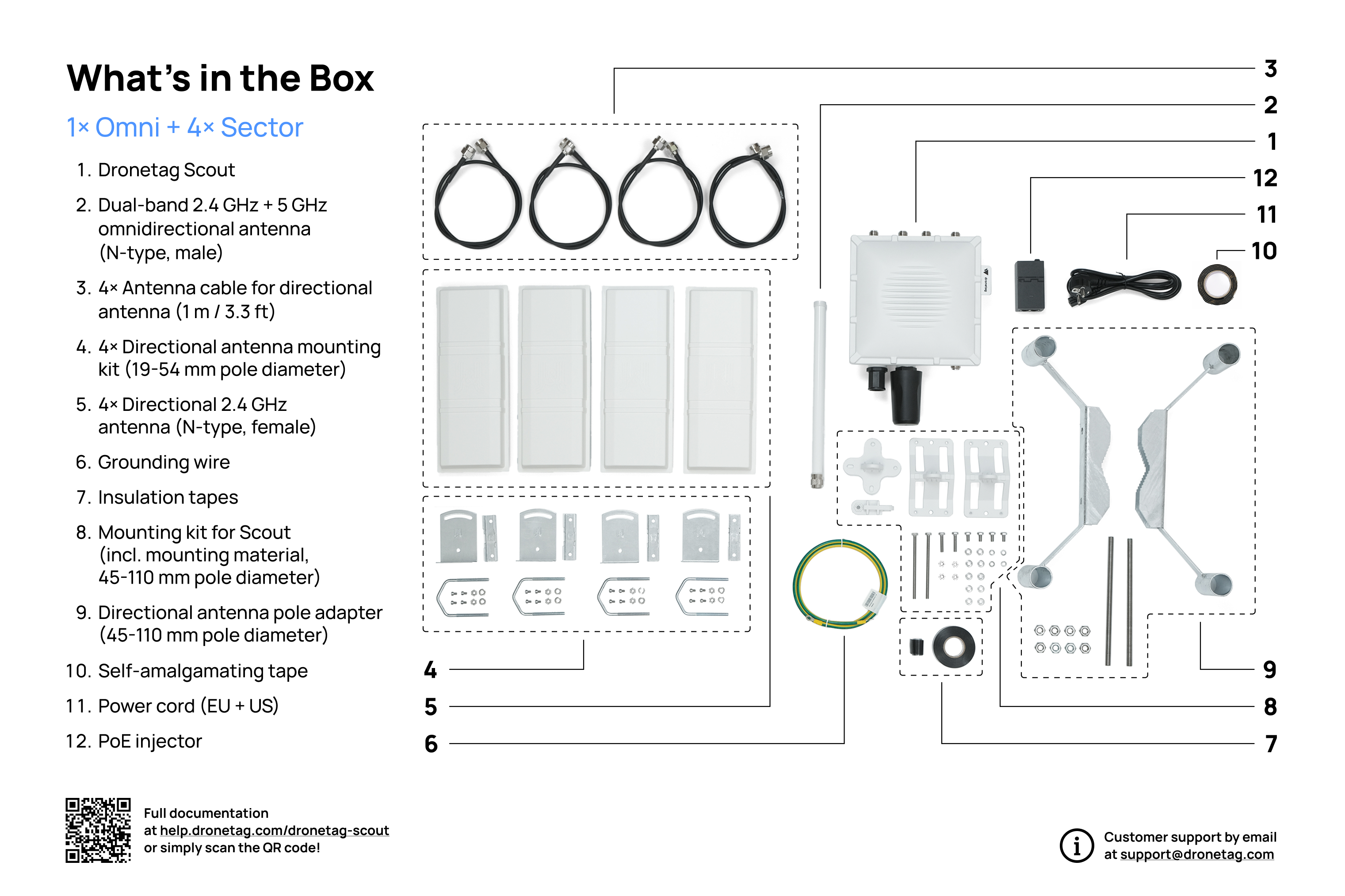
3D Model
- Scout (1× Omni + 4× 90° Sector) – extended configuration for maximum coverage and directional detection
👉 View 3D model
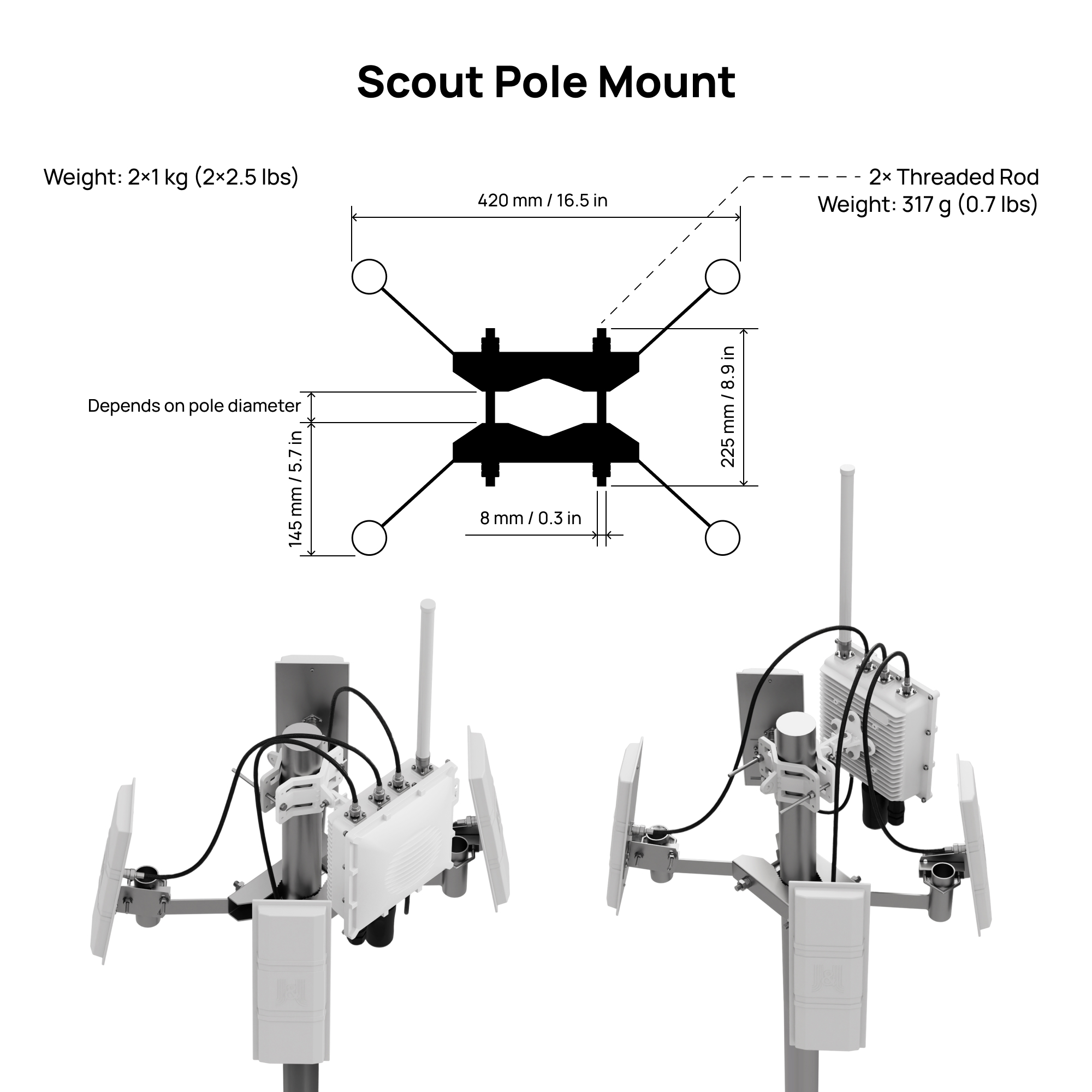
This Scout variant includes a holder for four directional antennas for free.
The Scout with directional antennas package comes in a box with adjustable height and has the following maximal dimensions:
450 mm x 350 mm x 250 mm / 17.7" x 13.8" x 9.8"
The actual height depends on the specific Scout configuration. This size ensures the contents are well-protected during transport while still being easy to handle.
Each package contains power cords with both EU and US plugs.
Installation Prerequisites
This section describes the requirements for successful deployment of the Scout.
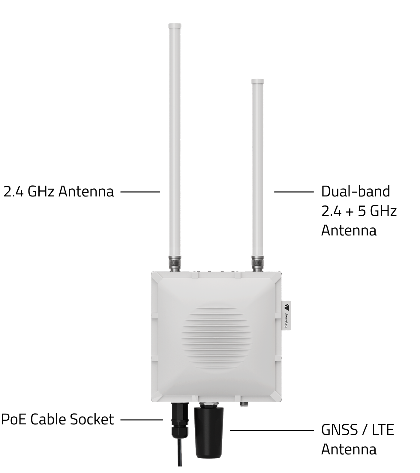
What is required to install and operate the Scout?
- Appropriate place to mount the Scout
- Pole in the desired place with a diameter of 45 – 110 mm
- Two 10 mm wrenches
- Power outlet or Ethernet available with supported PoE
- Ethernet cable dedicated for outdoor use (CAT5 and higher)
- Ability and equipment to crimp your Ethernet cable
- Safe and dry place for placing the PoE injector
- Local network which will be used to operate the Scout
- Ethernet port configured to 100 Mbit Full Duplex
- Computer to connect to local network to configure Scout
Deployment Step-by-Step Guide
This guide walks you through the full process of deploying your Dronetag Scout device—from unboxing to live drone detection in the field. Each step includes helpful links to relevant documentation, so you can get started quickly and confidently.
1. Unpack Your Scout Device
Begin by unboxing your Dronetag Scout and verifying that all components are present. Before physical deployment, connect the device to your local network to verify functionality.
2. Connect the PoE Injector to Power
Use the Power over Ethernet (PoE) injector included with your Scout.
Ensure that the injector matches the voltage and power specifications of the official Dronetag PoE injector to avoid damage.
The Scout PoE injector supports both EU and US power outlets and can be used with input voltages of 120 V or 240 V.
- Ethernet
- LTE
3. Plug in the Ethernet Cable and Connect to the Scout
Connect the Ethernet cable between the Scout and your network via the PoE injector. To access the management interface, you’ll need the device’s local IP address.
3 Plug in the Ethernet Cable and Connect to the Scout
Connect the Ethernet cable between the Scout and your network via the PoE injector. To access the management interface, you’ll need the device’s local IP address.
🔍 Find out how to locate the IP address
3.1 Insert a SIM Card and Configure APN
Before proceeding, ensure your SIM card is properly installed and configured for LTE connectivity. For detailed instructions on SIM card installation and LTE setup, please refer to our comprehensive guide here:
📘 SIM Card Installation and LTE Setup
This step is crucial to enable LTE functionality and ensure your Scout connects reliably to the mobile network.
Scout can be provided with connectivity by Dronetag; please check your ordering information before opening up the Scout. The unit comes pre-configured correctly and you don't need to do any configuration.
4. Access the Management Page
Open the Scout’s Management Page in your browser (e.g., https://[Scout-IP]).
Here, you can view diagnostics, network info, and configure operational parameters.
📘 Learn how to configure the network correctly
- Cloud Mode
- Sensor
5. Configure Cloud Mode
To use your Scout with Dronetag Cloud and the Dronetag App, follow these steps:
5.1 🧑💻 Create a Dronetag Account & Register the Device
- Go to dronetag.app or download the Dronetag app
- Sign up or log in.
- Add your Scout device using its serial number.
📘 Full guide to Cloud Mode & registration
6. Verify Functionality
Before final deployment, confirm the Scout is working properly.
☁️ Cloud Mode Test (App)
If you’re using Cloud Mode, test the connection and detection using the Dronetag App:
- Open dronetag.app (web or mobile)
- Log in to your account
- Navigate to your device
- Confirm:
- The Scout shows as Standby
- Live telemetry is updating
- Remote ID drones are visible if nearby
Avoid testing Scout close to devices using 2.4 GHz or 5 GHz frequency. Examples of these devices are the following:
- drone controllers
- mobile hotspots
- wearables
- modern in-car Wi-Fi systems such as Apple CarPlay and Android Auto
Basically it is every smart device using wireless communication.
5. Configure the Sensor Forwarder endpoint
As a start, study the sample source code of the possible integration of the Sensor mode. Choose the type of integration best suited for your needs.
6. 🛰️ Sensor Mode Test (Local Map)
Before full deployment, verify that your Scout is able to detect drone Remote ID signals. Quickly check the Remote ID drones visible to your Scout at https://<SCOUTIP>/map
🧪 Perform a basic test using the map
Avoid testing Scout close to devices using 2.4 GHz or 5 GHz frequency. Examples of these devices are the following:
- drone controllers
- mobile hotspots
- wearables
- modern in-car Wi-Fi systems such as Apple CarPlay and Android Auto
Basically it is every smart device using wireless communication.
7. Choose an Optimal Installation Location
Select a location that ensures minimal signal interference and maximum visibility to the sky.
📍 Best practices for site selection
8. Mount the Scout Securely
Physically install the Scout in your chosen location.
Use the mounting hardware provided or your own reliable outdoor mounting solution.
🔧 Follow the mounting instructions
9. Start Scanning for Drones!
You're now ready to begin real-time detection of Remote ID signals.
If you use Scout in Cloud Mode, head over to the Dronetag App to monitor live activity from your Scout device.
💡 Need Help?
If you encounter issues at any step, consult our Troubleshooting Guide for solutions to common problems, or contact support for direct assistance.
Choosing Location for Scout
What is the Right Location
To get the most out of your Scout, location matters - a lot.
- Choose a suitable and elevated spot for installation.
- The receiver’s performance relies heavily on a clear, unobstructed view of its surroundings.
- A rooftop, ideally the highest one in the area, often proves to be the perfect vantage point for maximum signal coverage.
📡 For optimal range and accuracy, avoid mounting the Scout too close to any devices that transmit on 2.4 GHz or 5 GHz frequencies - such as Wi-Fi routers or other radio systems.
Factors Influencing Remote ID Signal Reception
Signal reception isn’t just about hardware - it’s also about the environment. Several key factors can impact how well the Scout picks up Remote ID transmissions.
Ensuring Visual Line of Sight (VLOS)
• Physical obstacles between the drone and the Scout - like buildings, trees, or terrain - can block or weaken signals.
• When possible, install the Scout in a spot with a clear view in the direction where drone activity is expected.
Signals in the 2.4 GHz and 5 GHz Frequency Bands
• The Scout operates in frequency bands that are commonly shared with other technologies.
• Devices such as Wi-Fi routers, Bluetooth speakers, or even smart home hubs can cause interference.
• Keep the Scout as far away as possible from these types of devices.
Electromagnetic Noise
• All electronics generate a certain amount of background noise, which can interfere with sensitive receivers like the Scout.
• Avoid installing the Scout near AC units, inverters, solar power stations, or other large electrical systems.
Transmission Power of the Drone’s Remote ID Signal
• Not all drones are created equal - the power of the signal they transmit can vary greatly.
• This power level is defined by the drone manufacturer and local regulations, and while you can't control it, it's good to be aware that some drones may simply broadcast farther than others.
Mounting the Scout
Choose the Right Location
Before installing the Scout receiver, make sure you have the proper location and infrastructure ready. This will save you time and ensure optimal performance from the start.
What You’ll Need for Installation
To install the Scout, make sure you have the following:
-
A tall structure or mast/pole - the higher, the better.
Ideally on the highest rooftop in the area, with a clear line of sight in all directions.
The Scout cannot receive signals through buildings or large obstacles. -
A stable power source:
- Either a standard indoor power outlet near the Ethernet cable entry point, or
- A PoE (Power over Ethernet) injector if direct power access is not available.
The Scout has a low power consumption (under 10 W), so both options are easy to accommodate.
-
An outdoor-rated Ethernet cable (CAT5 or higher) with the ability to crimp RJ-45 connectors.
-
Minimal radio interference: Avoid placing the Scout close to Wi-Fi transmitters or other antennas operating at 2.4 GHz or 5 GHz.
Drone controllers, mobile hotspots, wearables, and modern in-car Wi-Fi systems such as Apple CarPlay and Android Auto. Basically it is every device using wireless communication.
Recommended Conditions
For best performance:
- Choose a high, unobstructed position — the higher, the larger the detection range.
- Avoid areas with dense urban obstacles, metallic surfaces, or sources of RF noise.
- Ensure the Scout has a clear line of sight toward open space — it will not detect signals behind walls or buildings.
- If you are unsure about the right location, contact our support.
Send us the address of the intended installation site or photos from the rooftop view, and we’ll help you verify signal conditions using satellite data (e.g., Google Earth) and identify any potential interference sources.
Step-by-Step Guide
Now that your location is ready, the power and network connection are prepared, and you’ve confirmed optimal conditions, follow these steps to mount and connect the Scout properly.
Carefully go through each step to ensure the best performance and long-term reliability of your installation.
Mount the Device
- To ensure optimal performance, the receiver should be mounted on an elevated structure like an existing pole, bracket, or mast.
- If no such structure is available, a tripod can be used.
Mount the device to the desired place. Remember that the higher the place is, the better Scout will receive the Remote ID signal coming from the drones. While mounting the Scout, stick with the mounting manual and strictly follow the local regulations for electrical installation and surge and lightning protection.
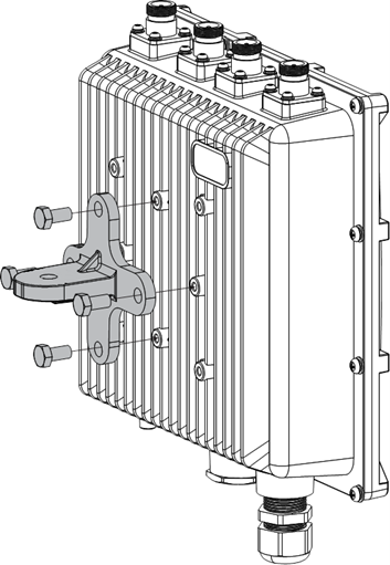
1. Fix a Cross Bracket to Scout
Fix the included cross bracket on the bottom of the enclosure with four (4) M6*12 bolts.
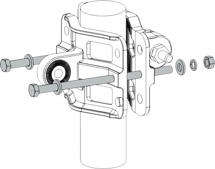
2. Mount the Pole Clamp
Place two (2) pieces of the clamp around the pole and tighten them with the included M6*110 bolts, washers, and nuts.
3. Connect the pole clamp and Scout
The pole clamp works for 45 – 110 mm diameter of pole and the cross bracket by securing the last piece of the mounting kit in place using M6*30 bolts, washers, and nuts.
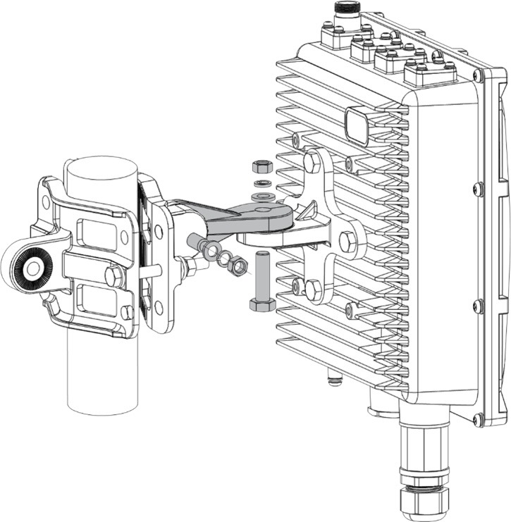
The Scout must be fixed so that antennas point perpendicular to the horizontal line.
Connect and Insulate the Cables
5. Connect the PoE cable
Please note that you will need the ability to crimp your own Ethernet cable with an RJ-45 connector for any setup and connection.
Crimp your own Ethernet Cable
Use only CAT5 (or above) cabling with outdoor rating.
- The non-LTE version of Scout receiver must be constantly connected to an internet router for data transmission to the Dronetag Cloud when used in Cloud Mode.
- The Scout must be connected to the same network as the computer used to perform the initial configuration.
The receiver is designed for outdoor use, housed in a weather-resistant case. The Ethernet cable must be threaded through a cable gland and crimped inside for a secure connection.
6. Connect the Ethernet cable using the PoE injector
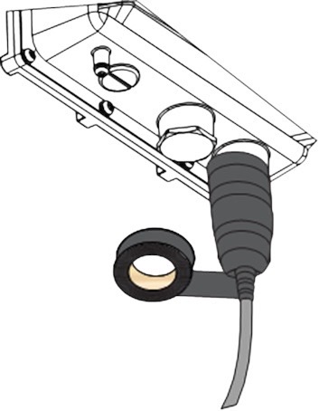
After the PoE cable is connected, insulate it with the included PVC tape:
Insulate the Ethernet Cable Connector
- Clean the surface area of the connector that will be wrapped. Wrap a layer of PVC tape with a 50% overlap according to the rotation direction of the connector. Continue wrapping the PVC tape to about 10 mm below the end of the connector.
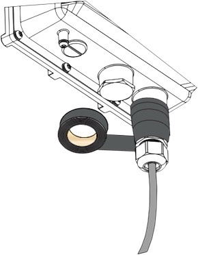
- Wrap three additional layers with PVC tape with natural uncoiling force and a 50% overlap. Make sure to cover the head and the tail of the connector.
Mounting the Antennas
This guide explains how to install the directional antenna mount for Dronetag Scout.
Follow the steps carefully to ensure a secure installation and reliable antenna performance.
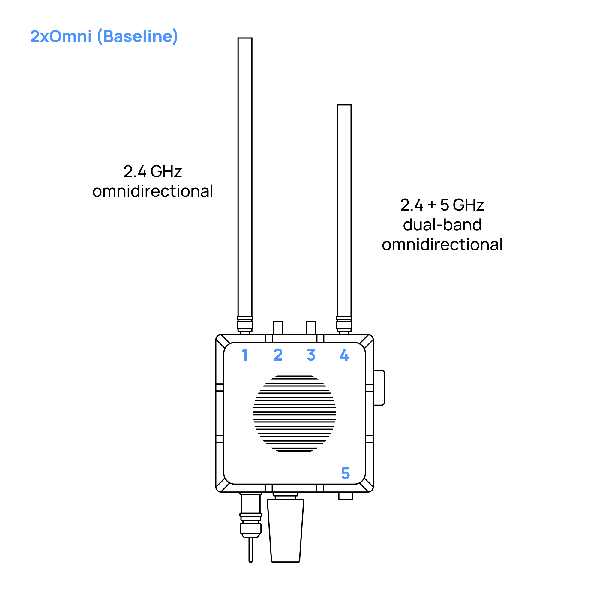
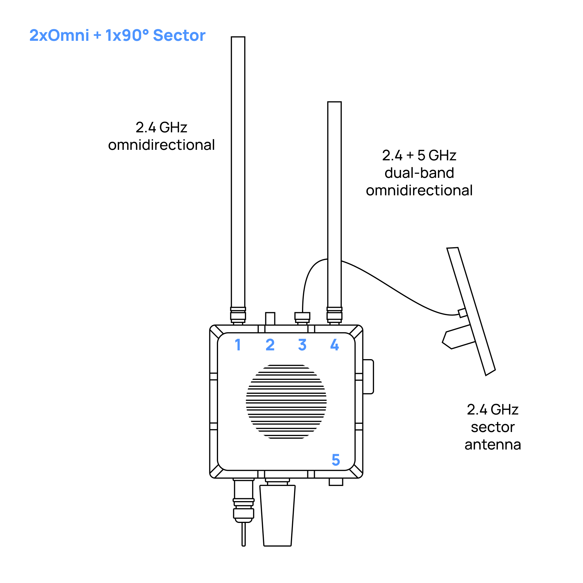
Antenna Connector Layout
- Scout Baseline - 2x Omnidirectional Antennas
- Scout with 2x Omnidirectional Antennas + 1x Sector (Directional) Antenna
- Scout with 2x Omnidirectional Antennas + 2x Sector (Directional) Antennas
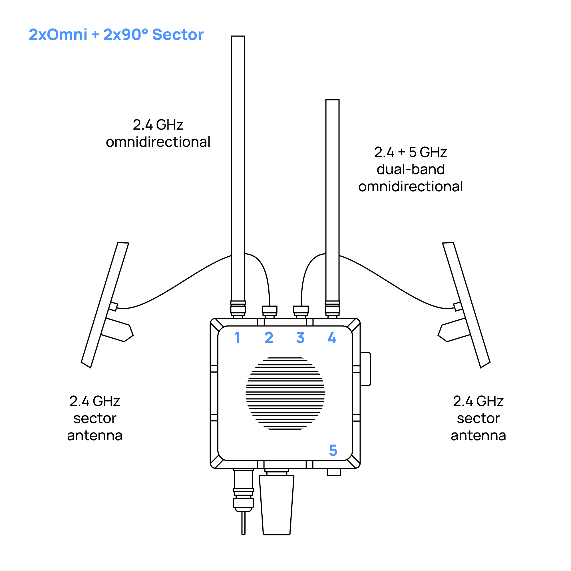
- Scout with 2x Omnidirectional Antennas + 3x Sector (Directional) Antennas
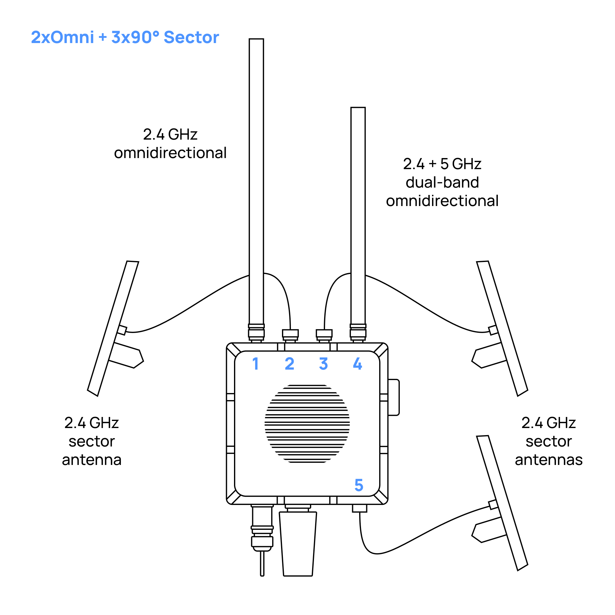
- Scout with 1x Omnidirectional Antenna + 4x Sector (Directional) Antennas
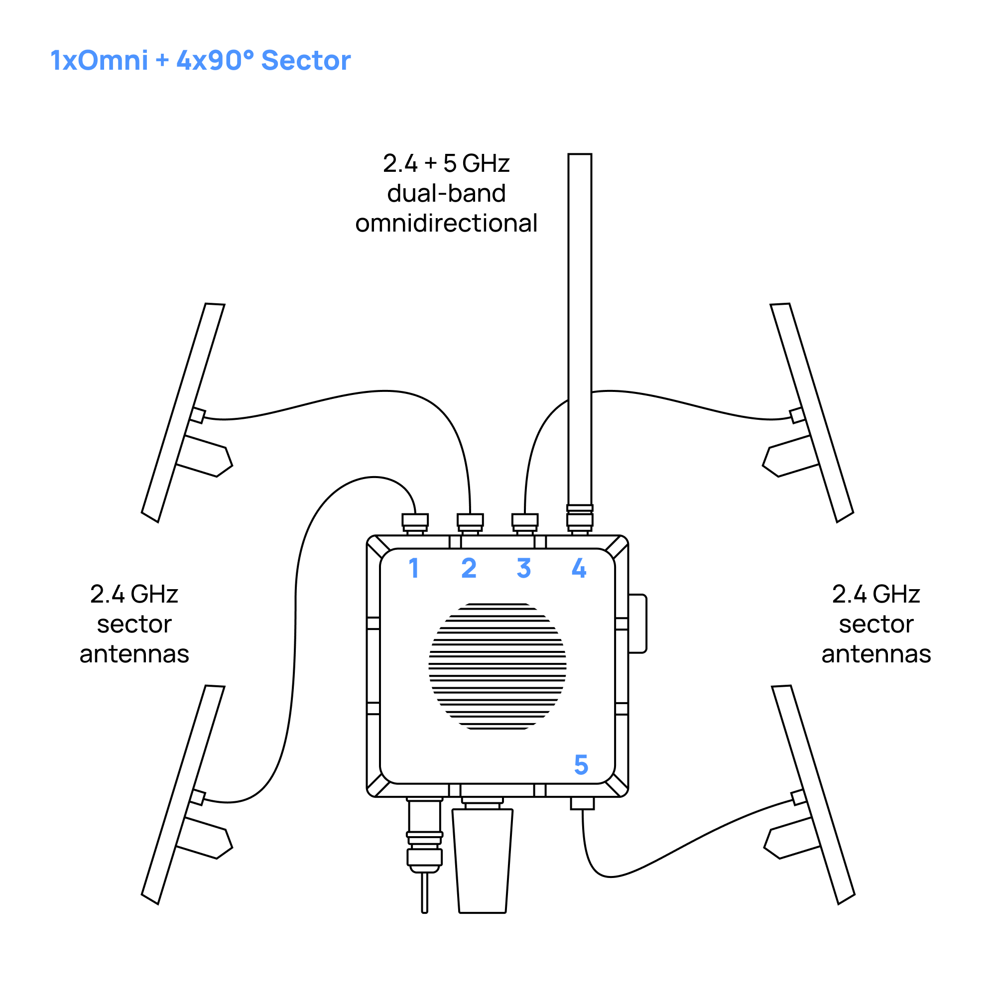
- Omnidirectional Antennas
- Holder for Four Directional Antennas
- Holder for Two Directional Antennas
- Directional Antennas with No Holder
Omnidirectional Antennas on Scout Baseline
3D Model
Mount the 2.4 GHz Antenna
Screw the antenna marked with the "1" sticker on its box to the connector marked with the same sticker
In case you lost the sticker with the number or forgot what the number of the antenna was: the longer antenna has to be mounted on the left side of the device from the front view.
Mount the Dual-Band Antenna
Screw the antenna marked with the "4" sticker on its box to the connector marked with the same sticker (the shorter antenna has to be mounted on the right side of the device from the front view)
In case you lost the sticker with the number or forgot what the number of the antenna was: the shorter antenna has to be mounted on the right side of the device from the front view.
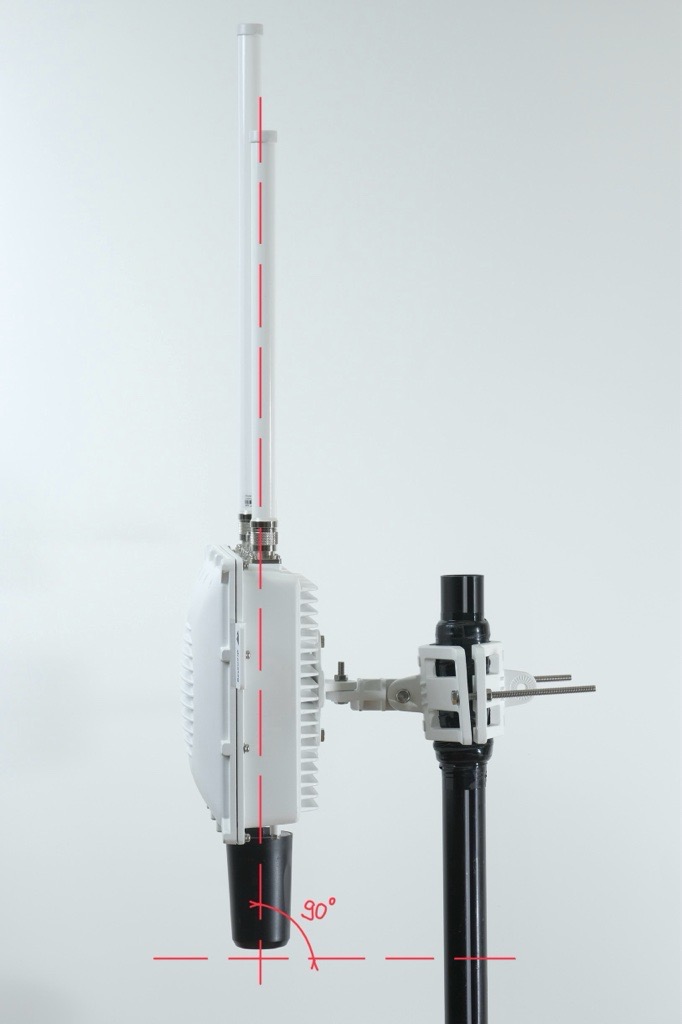
Correct Scout Orientation
The Scout must be mounted perpendicular to the ground.
This ensures the omnidirectional antennas have a clean and even field of view.
If the unit is tilted, one side of the antennas points into the sky and the other into the ground, which reduces performance.
Insulate connectors
-
Cut off about 50 cm of waterproof tape. Stretch it to double the length. Wrap three layers around the connector with a 50% overlap. Hold the tape in place with your hand for a few seconds.
-
Wrap three additional layers with PVC tape with natural uncoiling force and a 50% overlap. Make sure to cover the head and the tail of the connector.
Four Directional Antennas and One Omnidirectional Antenna on Scout
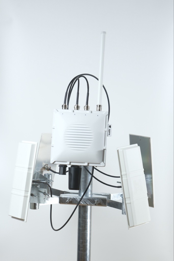
3D Model
In case you ordered Scout with four directional antennas, you automatically received a holder for these antennas, tailor-made to be used with Scout.
Each directional antenna covers a 90° sector horizontal and 30° sector vertical with 14 dBi gain, so by combining multiple panels you can shape coverage according to your needs.
This setup can significantly improve detection range and reliability in your target sector.
In the guide below, you’ll find step-by-step instructions on how to properly mount, align, and connect a directional antenna to your Scout device:
Each antenna box includes a number label. Make sure you know each antenna’s number so you can connect it to the correct connector later.
Directional antennas work best when there are no large obstacles nearby.
Avoid placing them close to satellite dishes, metal plates, masts, railings or any other surfaces that can block the signal and create blind spots.
For the best performance, the Scout and antennas should be mounted at the top of the pole, with a clear view in all directions.
1. Prerequisites
See prerequisites
Before starting the installation, make sure you have everything prepared.
Required Hardware
- A pole at the installation site with pole diameter 45 - 110 mm
- Directional antenna mount
- Dronetag Scout already installed on the same pole
Required Tools
- Two 17 mm wrenches for attaching the mount to the pole
- Two 10 mm wrenches for attaching antennas to the mount
- Antenna cables are 1 meter long. Plan the position so cables are not stretched or under tension.
- The directional antenna mount must be installed below the Scout, so the directional antennas don't block or shadow the omnidirectional antennas on the Scout.
2. Installing the Mount for Four Directional Antennas
Follow these steps after the Scout is already mounted on the pole:
Correct Scout Orientation
The Scout must be mounted perpendicular to the ground.
This ensures the omnidirectional antennas have a clean and even field of view.
If the unit is tilted, one side of the antennas points into the sky and the other into the ground, which reduces performance.
Prepare both steel counter-pieces
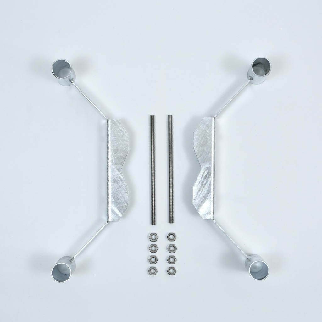
- Lay out the two mirrored steel counter-pieces.
- Insert the first threaded rod through the prepared holes and screw a nut onto each side.
- Do not tighten the nuts fully yet.
Installing this part can be difficult for one person.
An extra pair of hands helps a lot, and this is the only step in the entire installation where having two people is recommended.
If you need to install it alone, you can make the process easier by pre-assembling the counter-pieces:
Insert one threaded rod through the holes of both counter-pieces and screw the nuts on tightly.
This creates a stable assembly that can be placed onto the pole more easily.
- Once the pre-assembled counter-pieces are on the pole, insert the second threaded rod through the aligned holes and screw on the nuts.
Tighten the nuts on both threaded rods so that the gap between the counter-pieces is even on both sides.
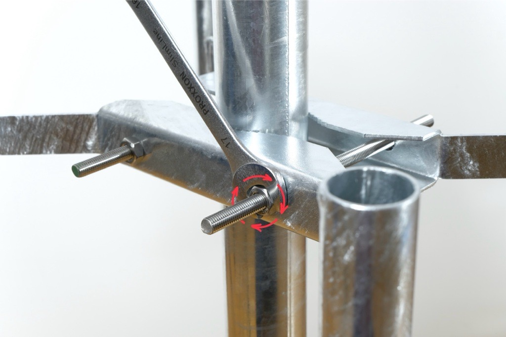
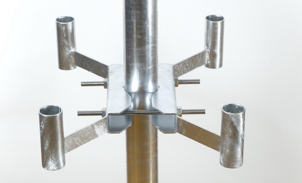
Tighten the nuts evenly
- Using the two 17 mm wrenches, tighten the nuts on both threaded rods.
- Check that the gap between the mount and both counter-pieces is even on both sides.
Secure with lock-nuts
- Once the mount is firmly attached and correctly aligned, screw on the lock-nuts to secure the position and prevent loosening.
3. Preparing Each Directional Antenna for Mounting
Prepare the L-shaped bracket
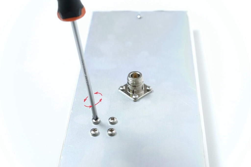
- Each antenna has four screws pre-installed on the backplate. Loosen and remove all four screws.
-
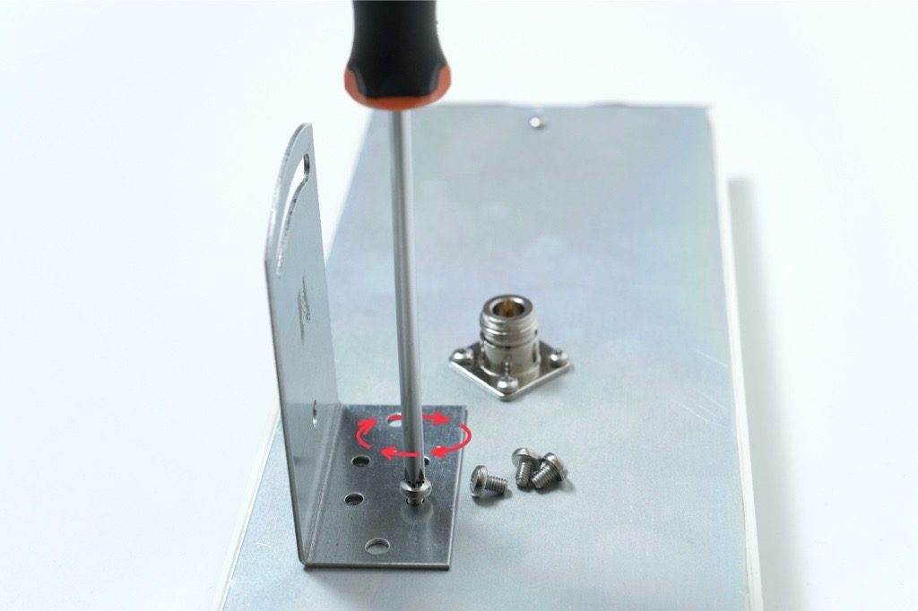
Place the L bracket onto the backplate so the vertical part of the bracket points toward the side of the antenna.
-
The bracket must not be centered and should sit offset to the side as shown in the photo below.
-
Align the holes and fasten the L bracket using the four original screws.
-
Tighten them firmly.
4. Attaching the Counter-Piece and U-shaped Rod
Attach the counter-piece to the L bracket
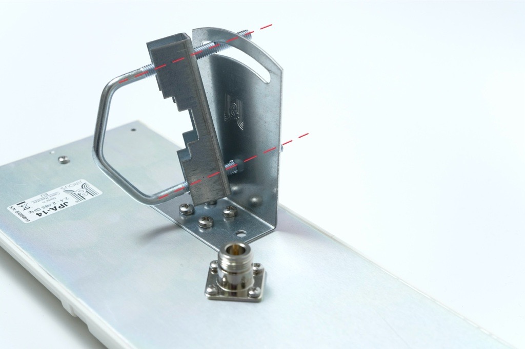
- Take the U-shaped threaded rod and the matching counter-piece with teeth.
- Place the toothed counter-piece directly against the L bracket, aligning the holes.
- Insert the U-shaped threaded rod through both aligned holes.
Add washers and nuts loosely
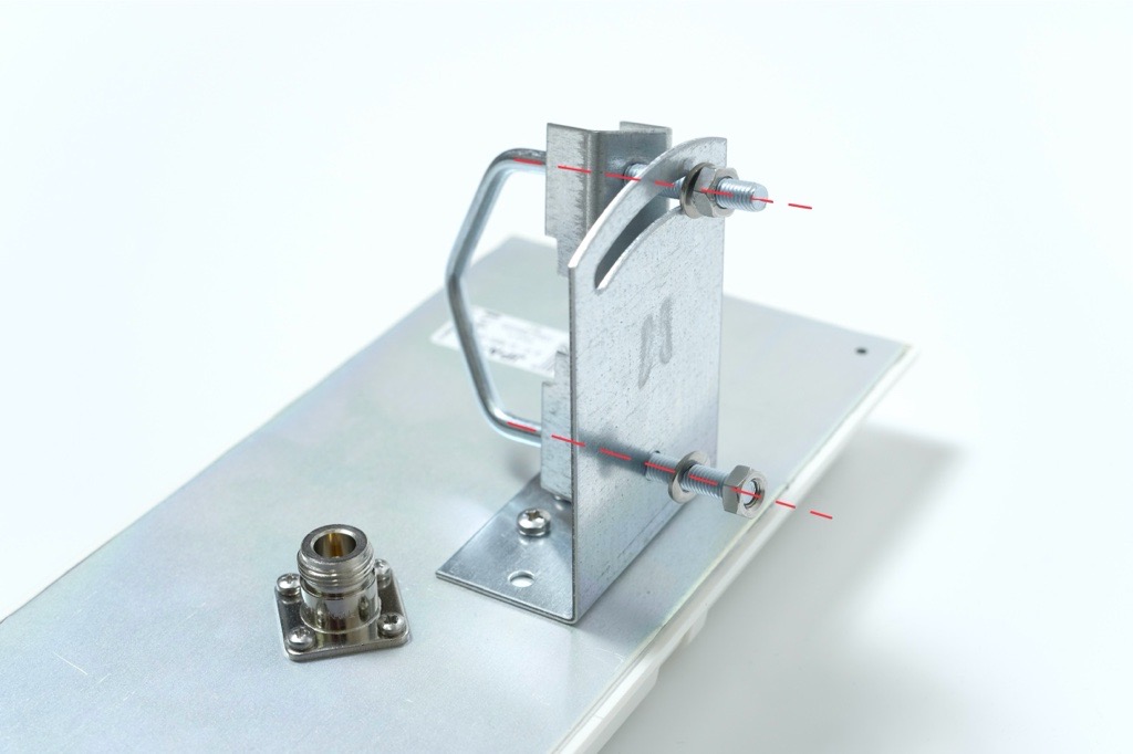
- Place washers and nuts onto both ends of the threaded rod.
- Tighten the nuts only lightly so the assembly stays together while allowing movement.
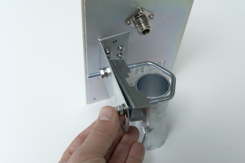
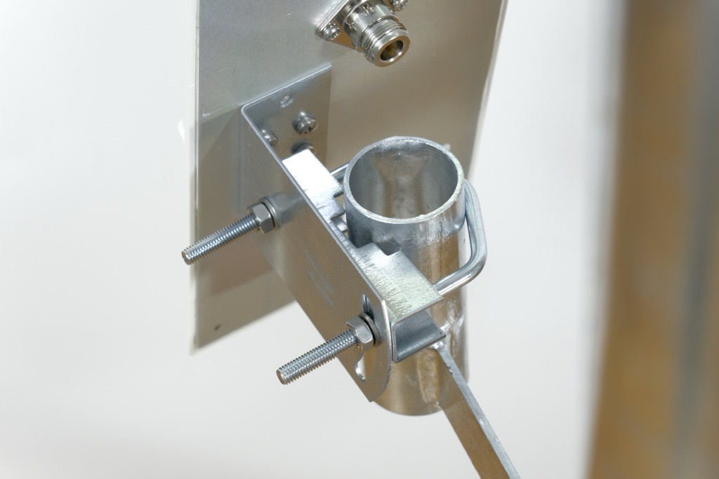
5. Mounting the Antenna onto the Holder
Position the antenna on the holder
- Take the antenna assembly and place it onto the directional antenna holder mounted on the pole.
- Slide the U-shaped threaded rod into the corresponding openings on the holder.
Do not mount the antenna too far down the holder.
The farther it is from the edge of the pole, the harder it becomes to access and tighten the mounting hardware.
For best installation comfort and stability, place the antenna approximately 1 cm (about ½ inch) below the top edge of the tube.
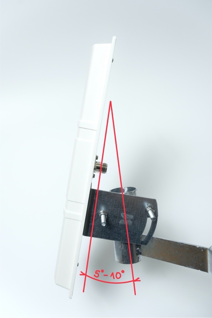
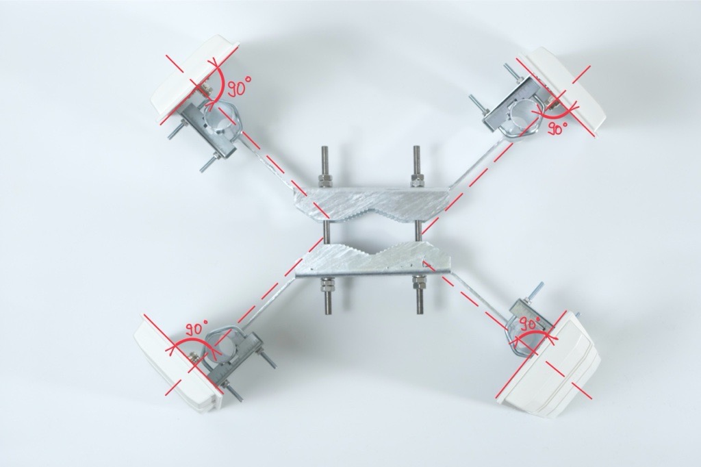
Set the antenna angle
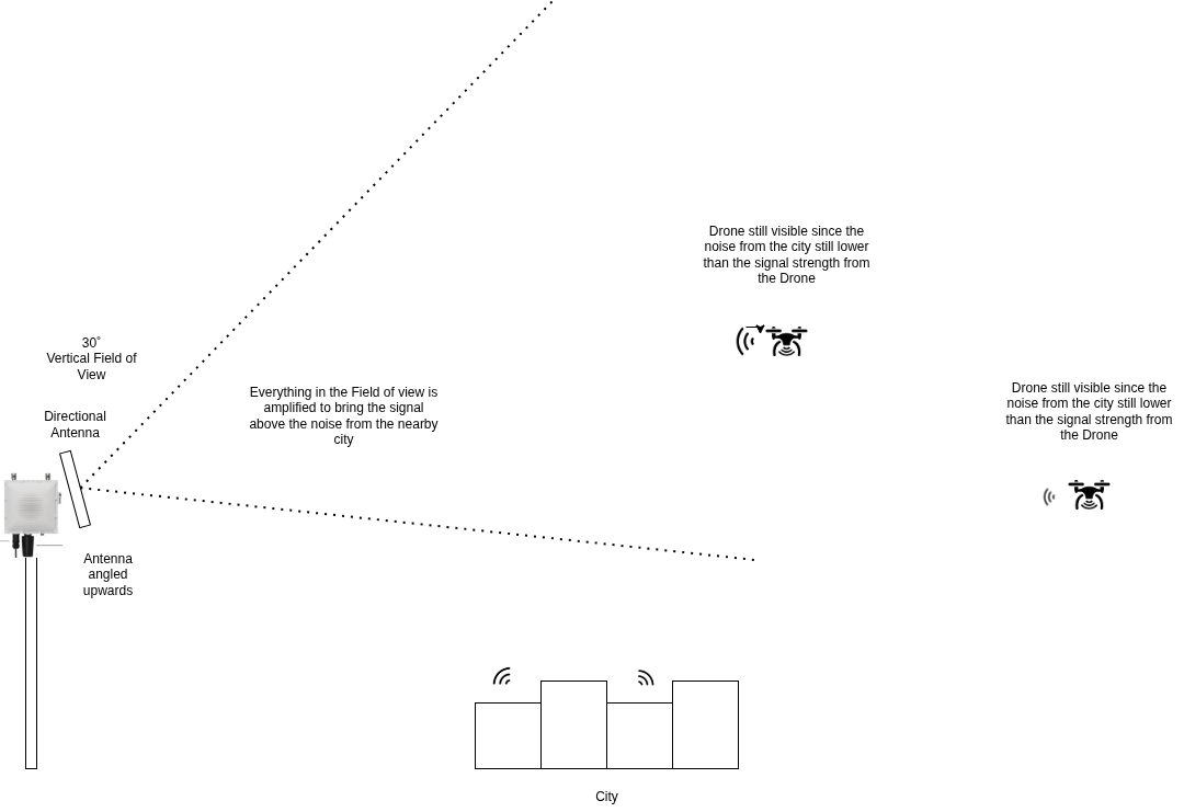
- Adjust the tilt of the antenna to between plus 5° and plus 10° above the horizon.
If the environment includes higher obstacles such as buildings, hills or trees, select a steeper angle within this range.
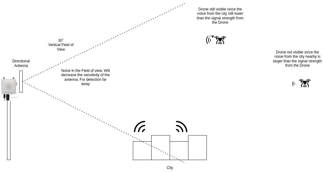
This is super-important when these antennas are installed in a city environment, where using this antenna angle can prevent interference with other signals.
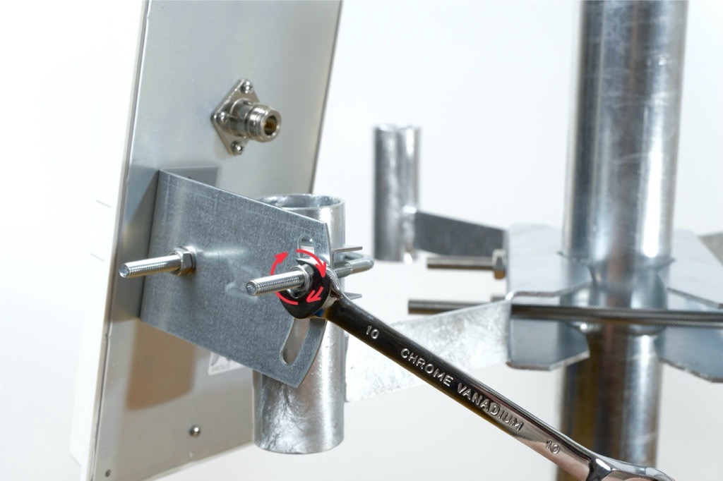
Tighten all nuts
- Once the antenna is positioned correctly, tighten all nuts firmly using the 10 mm wrenches.
- Ensure the antenna is stable and does not shift.
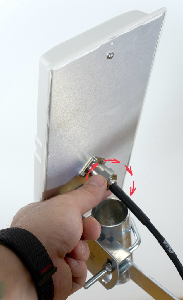
6. Connecting the Antennas to the Correct Ports
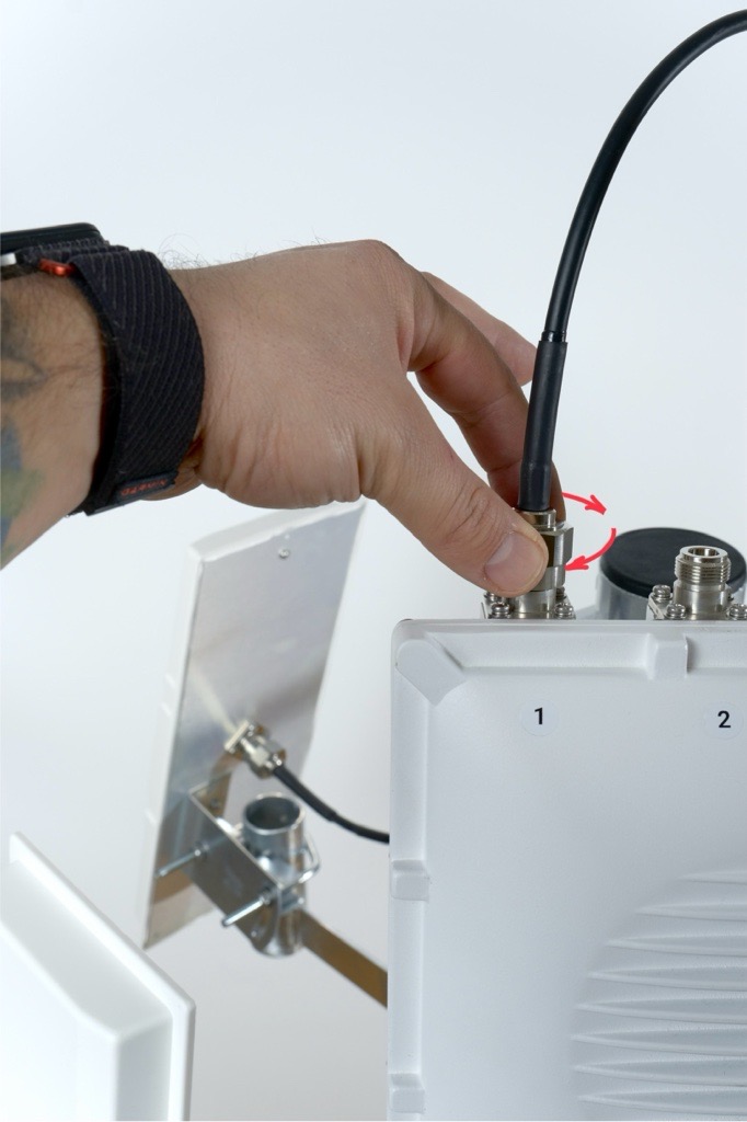
Match antenna numbers
Each antenna box includes a number label.
Connect the antenna cable to the RF port with the matching number on the Scout.
The numbers must match.
Route the antenna cables carefully so they are not stretched, pinched or rubbing against sharp edges.
Remember that the installation will be exposed to real weather. Rain, ice, snow, falling branches or even birds landing on the pole can put extra stress on the cables.
Keep the cables loose enough to move slightly, avoid tight bends and always guide them along the pole or the mount in a way that prevents tension. Good cable management helps prevent damage, signal loss, and long-term wear.
Pro tip: Plan the cable paths before tightening anything. A clean layout now saves a lot of pain later.
- Antenna nuts are made to be tightened by hand. In case you want to tighten them with a wrench, don't tighten them more than 1.5 Nm (13 inch pounds).
7. Weatherproofing the Connections
Seal the connectors
- After all antennas are mounted and tested, seal each RF connector with the supplied PVC tape.
- Wrap the tape tightly around the connector three times.
- The tape should overlap itself by at least fifty percent of its width and extend beyond the connector to prevent moisture from entering.
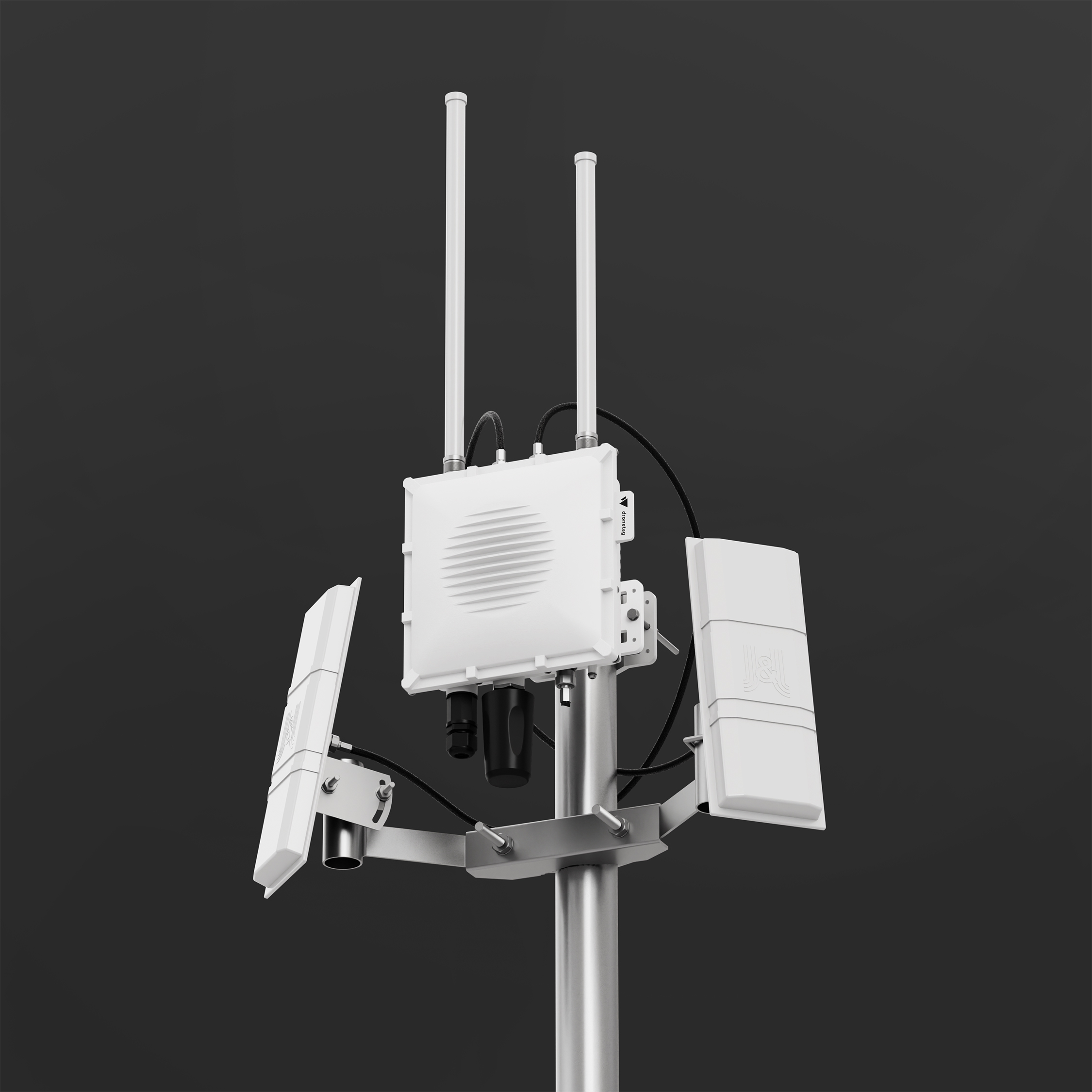
Two Directional Antennas and Two Omnidirectional Antennas on Scout
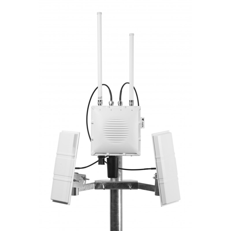
The holder for two directional antennas is tailor-made to be used with Scout.
Each directional antenna covers a 90° sector horizontal and 30° sector vertical with 14 dBi gain, so by combining multiple panels you can shape coverage according to your needs.
This setup can significantly improve detection range and reliability in your target sector.
- In the guide below, you’ll find step-by-step instructions on how to properly mount, align, and connect a directional antenna to your Scout device.
Each antenna box includes a number label. Make sure you know each antenna’s number so you can connect it to the correct connector later.
Directional antennas work best when there are no large obstacles nearby.
Avoid placing them close to satellite dishes, metal plates, masts, railings or any other surfaces that can block the signal and create blind spots.
For the best performance, the Scout and antennas should be mounted at the top of the pole, with a clear view in all directions.
1. Prerequisites
See prerequisites
Before starting the installation, make sure you have everything prepared.
Required Hardware
- A pole at the installation site with pole diameter 45 - 110 mm
- Directional antenna mount
- Dronetag Scout already installed on the same pole
Required Tools
- 17 mm wrench for attaching the mount to the pole
- Two 10 mm wrenches for attaching antennas to the mount
- Antenna cables are 1 meter long. Plan the position so cables are not stretched or under tension.
- The directional antenna mount must be installed below the Scout, so the directional antennas don't block or shadow the omnidirectional antennas on the Scout.
2. Installing the Mount for Four Directional Antennas
Package Contents
The mounting kit includes:
- 1× Mount for two directional antennas
- 1× U-shaped threaded rod (compatible with poles Ø 45–110 mm)
- 4× Nuts (17 mm wrench)
- 2× Washers
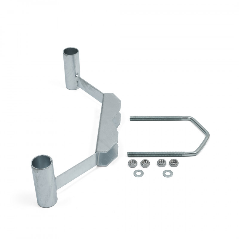
Follow these steps after the Scout is already mounted on the pole:
Check for Correct Scout Orientation
The Scout must be mounted perpendicular to the ground.
This ensures the omnidirectional antennas have a clean and even field of view.
If the unit is tilted, one side of the antennas points into the sky and the other into the ground, which reduces performance.
Holder installation
1. Place the mount against the pole (mast or pipe) with a diameter of 45–110 mm.
2. Wrap the U-shaped threaded rod around the pole and insert it through the mounting holes in the mount.
3. Place the washers and nuts onto both ends of the threaded rod.
4. Before tightening, rotate the mount so it is facing the intended direction of antenna coverage.
5. Tighten both nuts evenly using a 17 mm wrench until the mount is firmly secured.
3. Preparing Each Directional Antenna for Mounting
Prepare the L-shaped bracket
- Each antenna has four screws pre-installed on the backplate. Loosen and remove all four screws.
-
Place the L bracket onto the backplate so the vertical part of the bracket points toward the side of the antenna.
-
The bracket must not be centered and should sit offset to the side as shown in the photo below.
-
Align the holes and fasten the L bracket using the four original screws.
-
Tighten them firmly.
4. Attaching the Counter-Piece and U-shaped Rod
Attach the counter-piece to the L bracket
- Take the U-shaped threaded rod and the matching counter-piece with teeth.
- Place the toothed counter-piece directly against the L bracket, aligning the holes.
- Insert the U-shaped threaded rod through both aligned holes.
Add washers and nuts loosely
- Place washers and nuts onto both ends of the threaded rod.
- Tighten the nuts only lightly so the assembly stays together while allowing movement.
5. Mounting the Antenna onto the Holder
Position the antenna on the holder
- Take the antenna assembly and place it onto the directional antenna holder mounted on the pole.
- Slide the U-shaped threaded rod into the corresponding openings on the holder.
Do not mount the antenna too far down the holder.
The farther it is from the edge of the pole, the harder it becomes to access and tighten the mounting hardware.
For best installation comfort and stability, place the antenna approximately 1 cm (about ½ inch) below the top edge of the tube.
Set the antenna angle
- Adjust the tilt of the antenna to between plus 5° and plus 10° above the horizon.
If the environment includes higher obstacles such as buildings, hills or trees, select a steeper angle within this range.
This is super-important when these antennas are installed in a city environment, where using this antenna angle can prevent interference with other signals.
Tighten all nuts
- Once the antenna is positioned correctly, tighten all nuts firmly using the 10 mm wrenches.
- Ensure the antenna is stable and does not shift.
6. Connecting the Antennas to the Correct Ports
Match antenna numbers
Each antenna box includes a number label.
Connect the antenna cable to the RF port with the matching number on the Scout.
The numbers must match.
Route the antenna cables carefully so they are not stretched, pinched or rubbing against sharp edges.
Remember that the installation will be exposed to real weather. Rain, ice, snow, falling branches or even birds landing on the pole can put extra stress on the cables.
Keep the cables loose enough to move slightly, avoid tight bends and always guide them along the pole or the mount in a way that prevents tension. Good cable management helps prevent damage, signal loss, and long-term wear.
Pro tip: Plan the cable paths before tightening anything. A clean layout now saves a lot of pain later.
- Antenna nuts are made to be tightened by hand. In case you want to tighten them with a wrench, don't tighten them more than 1.5 Nm (13 inch pounds).
7. Weatherproofing the Connections
Seal the connectors
- After all antennas are mounted and tested, seal each RF connector with the supplied PVC tape.
- Wrap the tape tightly around the connector three times.
- The tape should overlap itself by at least fifty percent of its width and extend beyond the connector to prevent moisture from entering.
Directional Antennas without Holder
While Scout comes with omnidirectional antennas by default, you can also equip it with directional antennas for focused monitoring in a specific area.
Each directional antenna covers a 90° sector horizontal and 30° sector vertical with 14 dBi gain, so by combining multiple panels you can shape coverage according to your needs.
This setup can significantly improve detection range and reliability in your target sector.
In the guide below, you’ll find step-by-step instructions on how to properly mount, align, and connect a directional antenna to your Scout device.
1. Mounting the Bracket on Scout
The package includes a mounting bracket for poles with a diameter of 19–54 mm.
Ideally, install the antenna outdoors with a clear line of sight to the monitored sector.
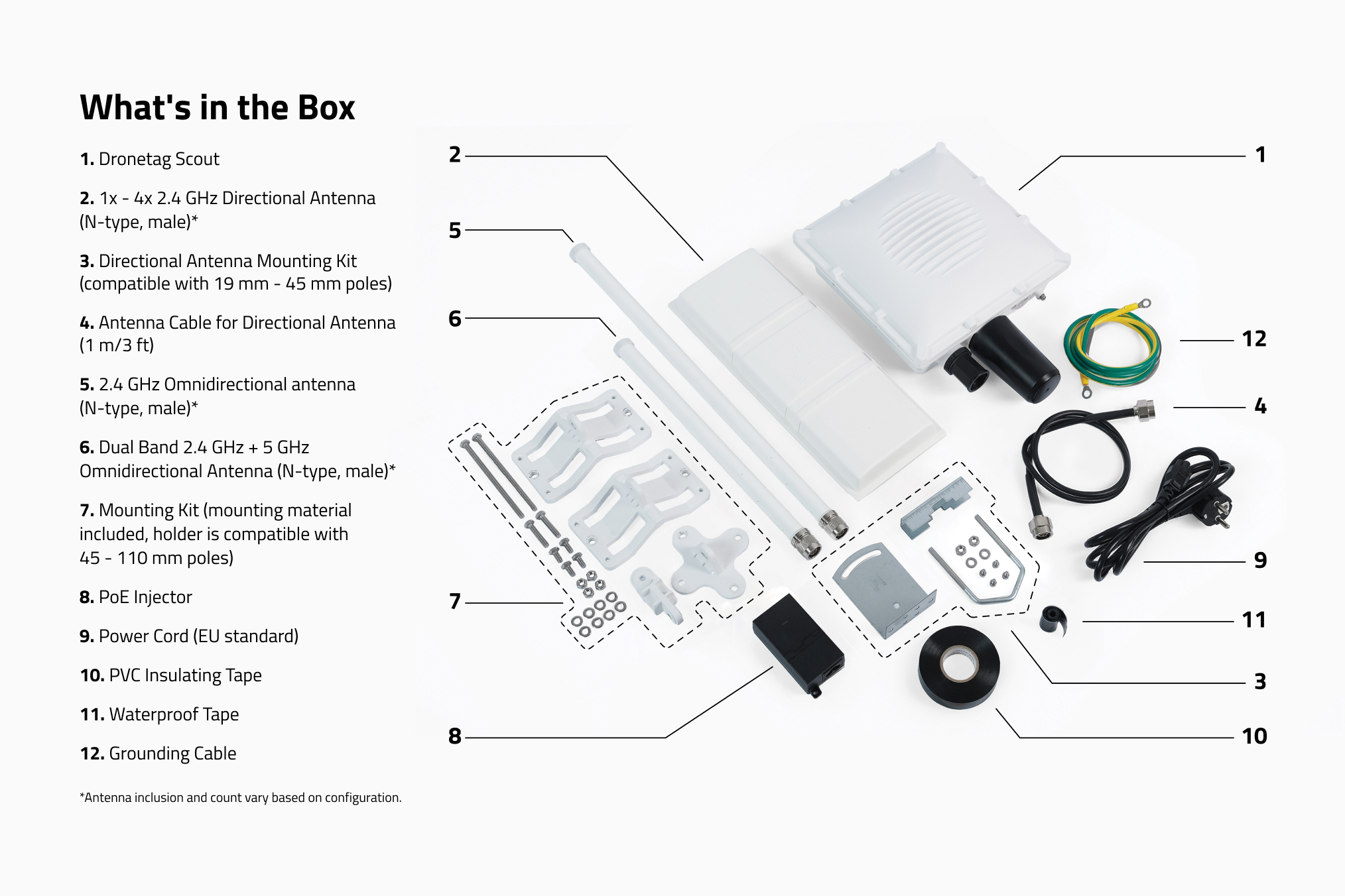
Items 2, 3 and 4 in the picture are needed to install the directional antenna.
2. Attaching the L-Bracket to Antenna Body
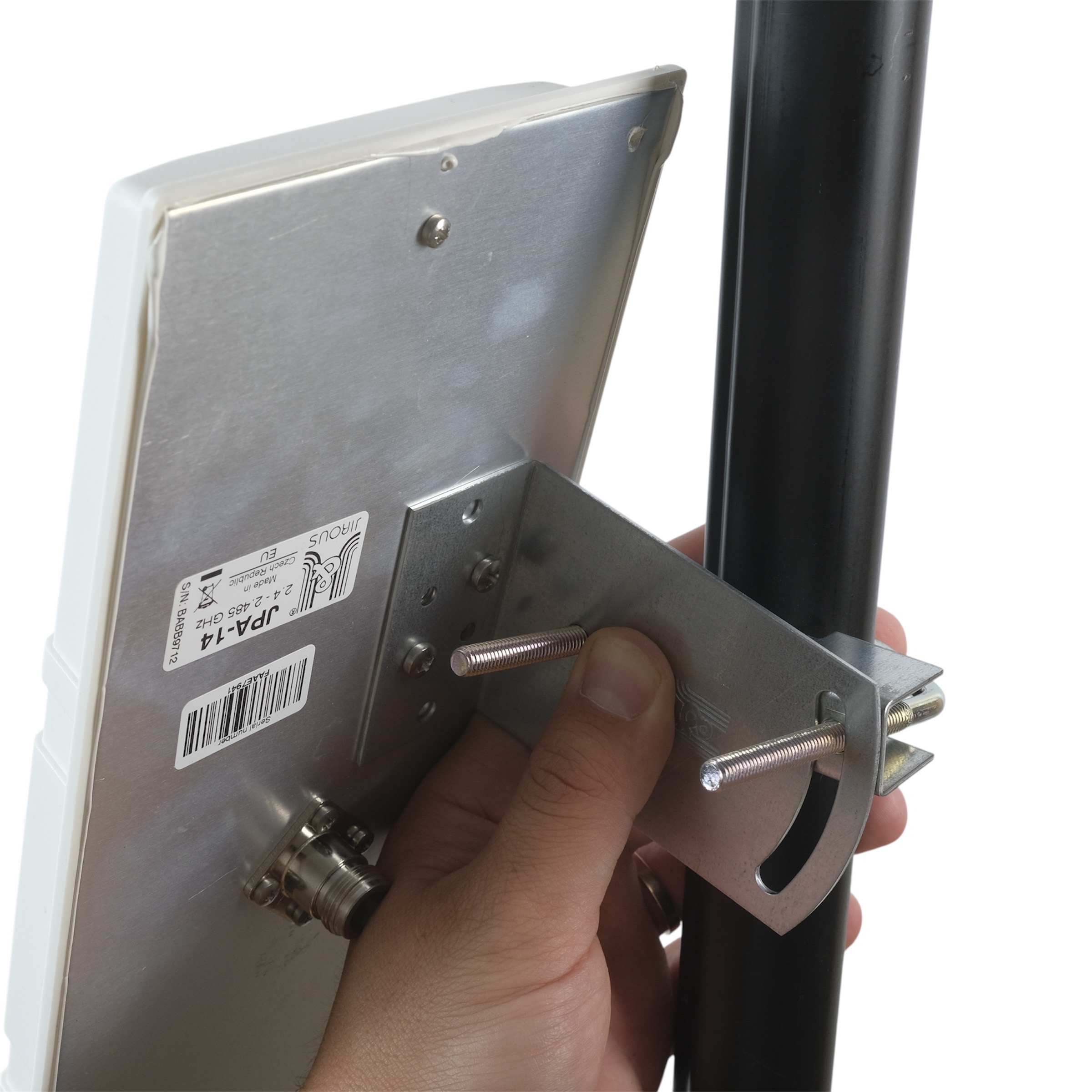
First, screw the L-bracket onto the back side of the antenna.
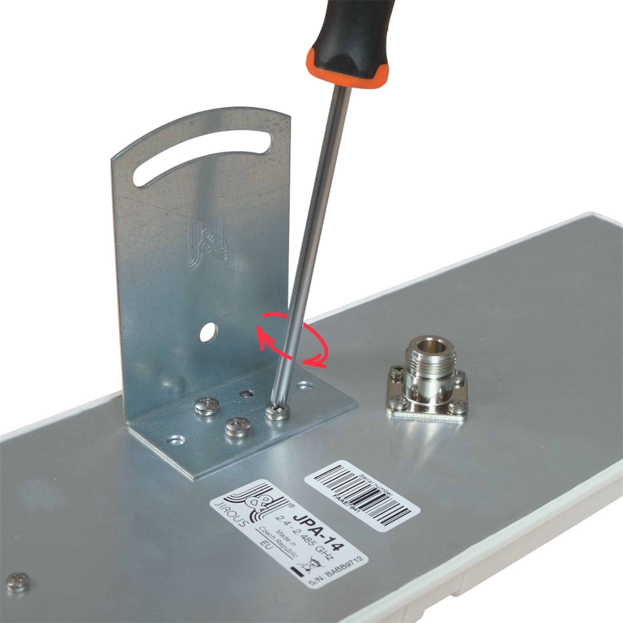
3. Installing the U-Bolt to the pole
Place the U-bolt with the washer on the pole first, and then attach the antenna panel with the mounted L-bracket.
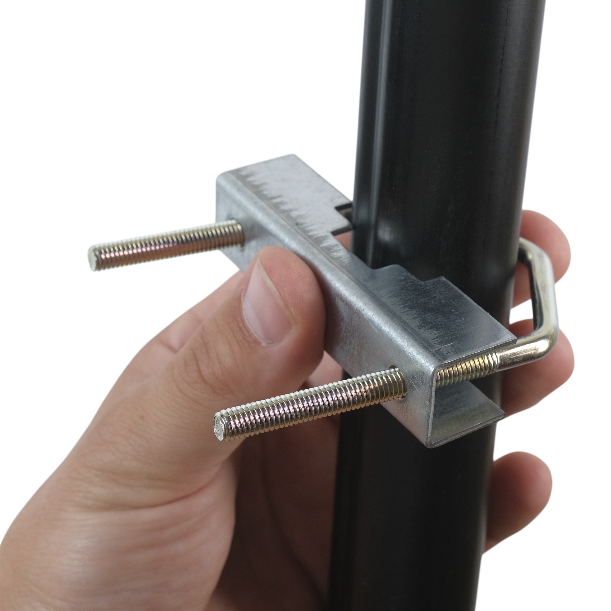
4. Tightening the Nuts
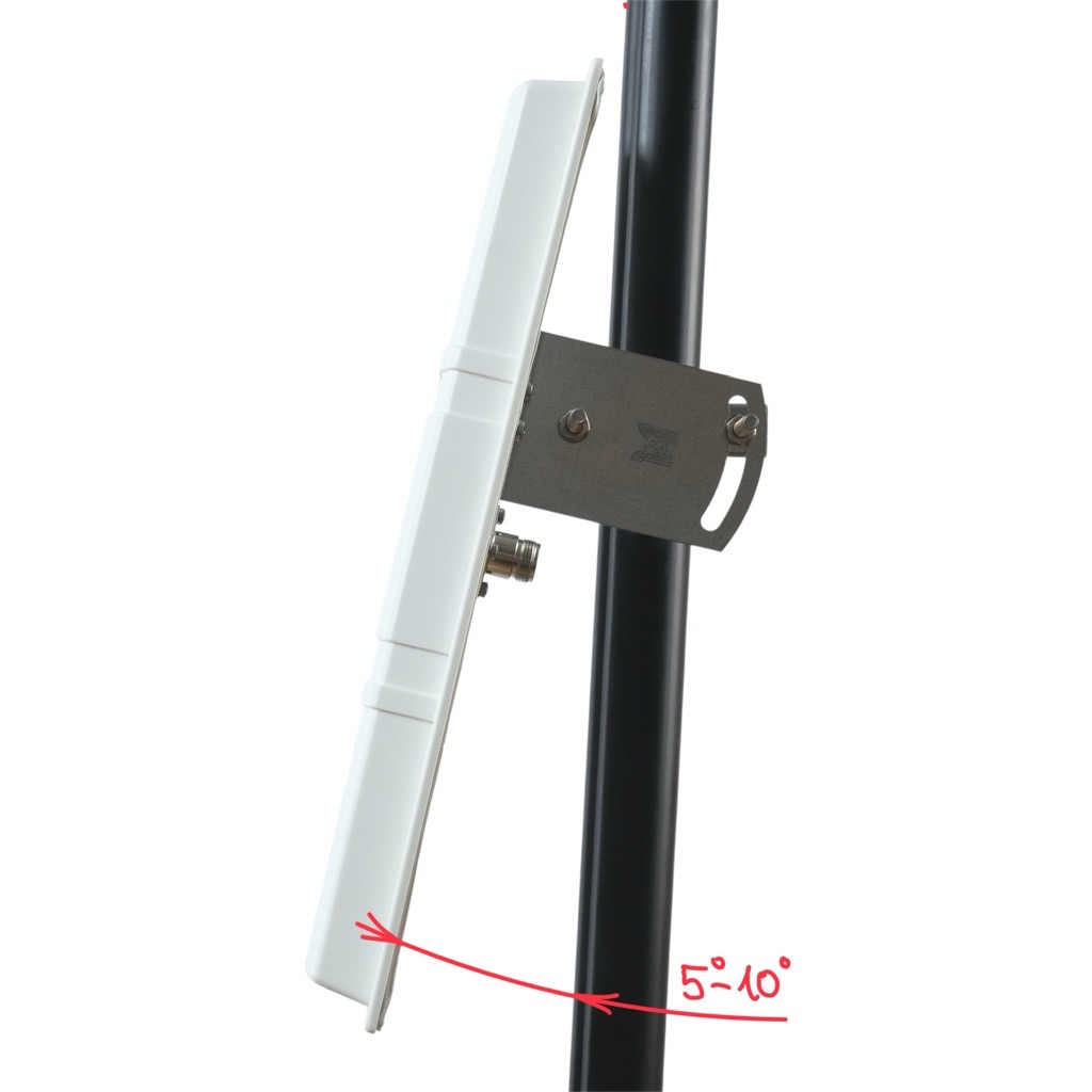
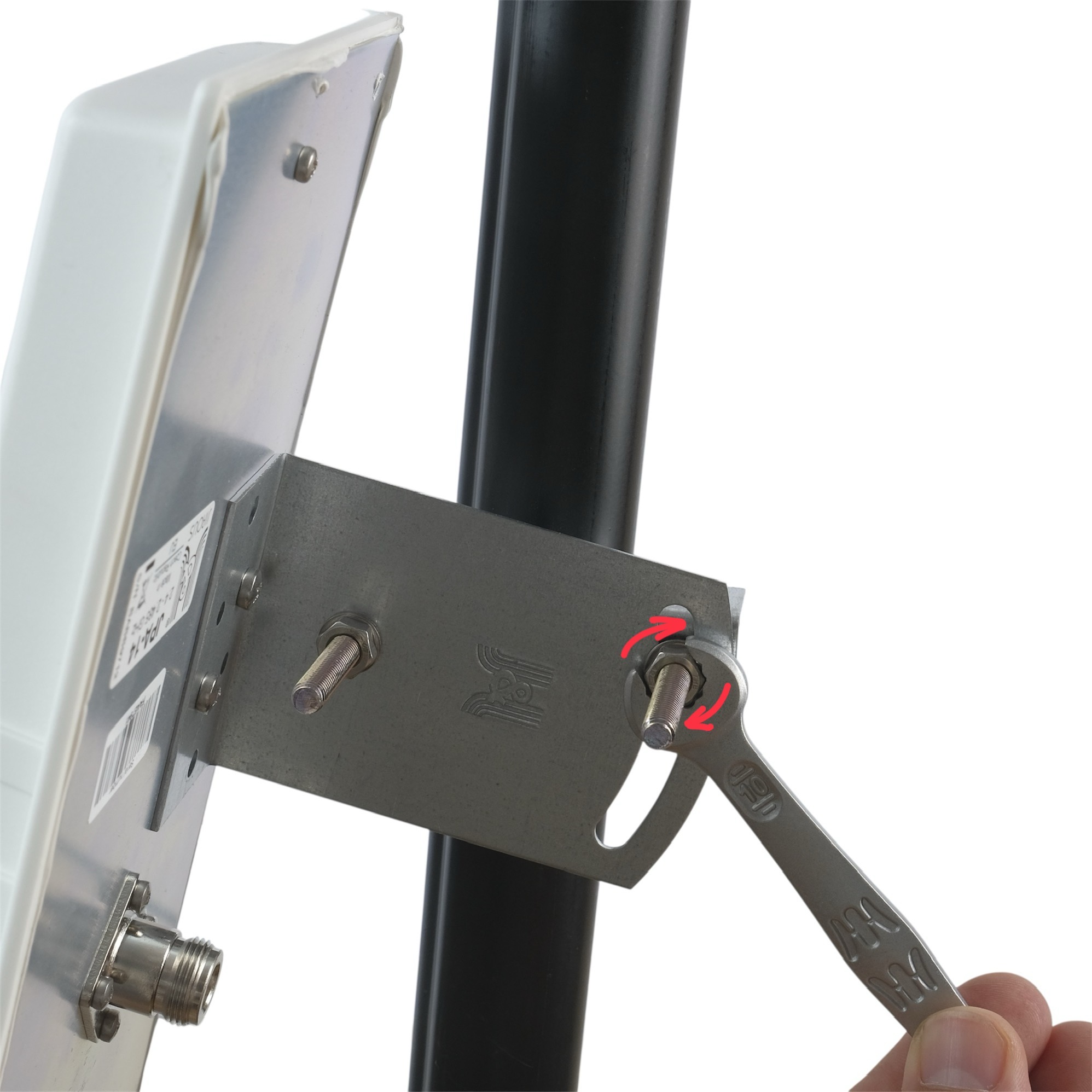
Tighten the nuts so that the antenna points 5–10° above the horizon in the target direction and then tighten.
5. Alignment
The front (flat) side of the panel must face the monitored sector.
Fine-tune the direction after connecting and checking signal levels in the app.
Important:
Make sure to align the directional antenna correctly. Avoid pointing it toward strong interference sources or other antennas.
Do not aim it at buildings or dense obstacles such as trees or skyscrapers — keep a clear line of sight to the monitored area for the best performance.
Tip:
Better placement = better signal. Avoid obstacles such as walls, trees, or metal structures.
Note:
In the following images, you can find an explanation of why it is important to set directional antennas at an angle of 5°–10° above the horizon.
6. Cabling
The antenna comes with a 1 m cable included.
Ensure the cable is not bent, especially near the connectors, and that it has enough slack to move freely — avoid sharp bends.
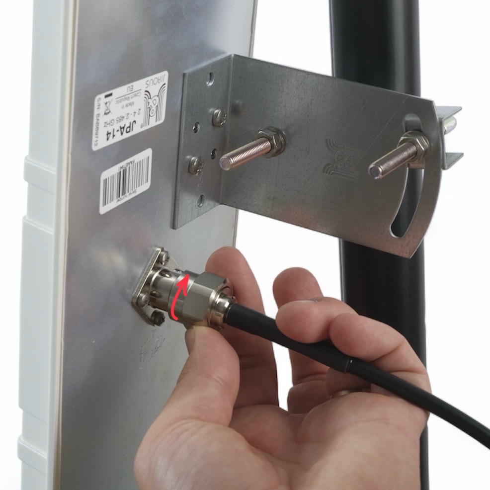
Sharp bends or excessive tension on the cable may damage the connectors and reduce signal quality.
7. Connecting Antennas to Scout
Plug the cable into the appropriate N-type port on the Scout.
Every connector and antenna is labeled with a number indicating its designated port. Ensure that each antenna is connected to the matching port number.
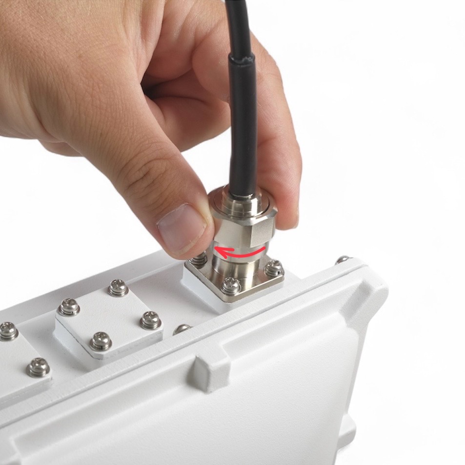
To attach antennas to correct connectors check the Antenna Connector Diagram chapter at the top of this page.
8. Insulate connectors
-
Cut off about 50 cm of waterproof tape. Stretch it to double the length. Wrap three layers around the connector with a 50% overlap. Hold the tape in place with your hand for a few seconds.
-
Wrap three additional layers with PVC tape with natural uncoiling force and a 50% overlap. Make sure to cover the head and the tail of the connector.
9. Check & Secure
Re-tighten all screws, check direction and stability of the antenna.
In windy areas, we recommend using additional reinforcement.
If you are unsure about your antenna installation, feel free to contact us on support@dronetag.com and send us photos and location of your Scout installation.
Inserting the SIM Card
If you will operate the LTE version without connectivity ordered, plug your SIM card in first — OTHERWISE SKIP THIS STEP
To successfully change the SIM card and configure the APN, please follow these steps carefully. Adhere to this guide to ensure the process is completed correctly.
The new SIM card used in the Scout must not be protected by a PIN code.
Step-by-Step Guide:
-
Disconnect the Scout from the Ethernet connection (which also serves as the power source).
-
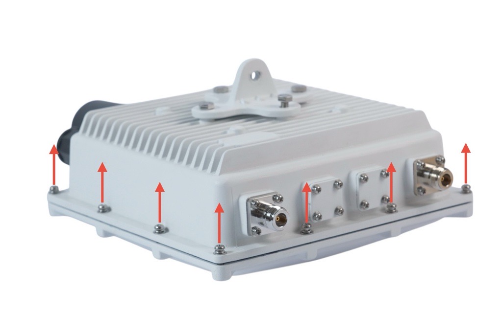
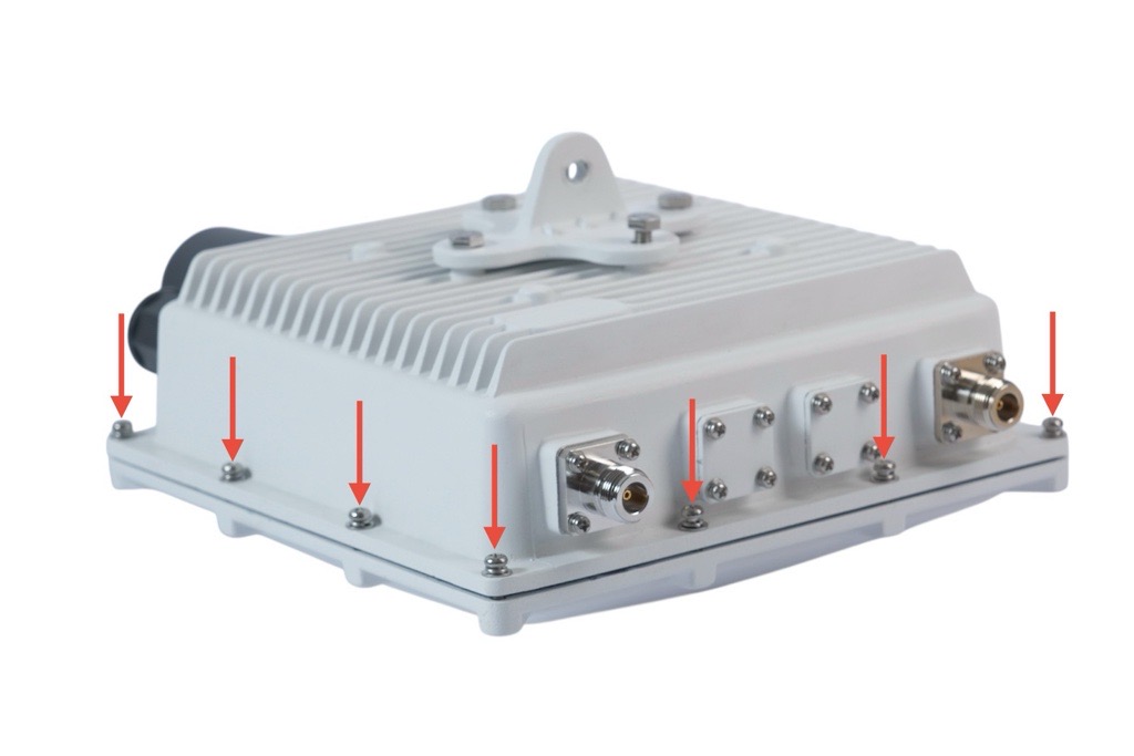
Unscrew all 12 bolts around the device perimeter.
Use a screwdriver that fits the bolts correctly to avoid damage. -
Carefully flip the device over.
-
Remove the cover and disconnect the micro-USB cable inside the device (1).
Before plugging the micro-SIM card in, ensure the SIM card works by testing it in a mobile phone to verify it is active and has no PIN lock.
Do not use a triple-cut (multi-size punch-out) SIM card. The stepped edges can catch on the connector contacts and damage them — use a proper single-size micro-SIM.
- Gently slide the micro-SIM card into the connector (2) — do not press on it or attempt to open the connector.
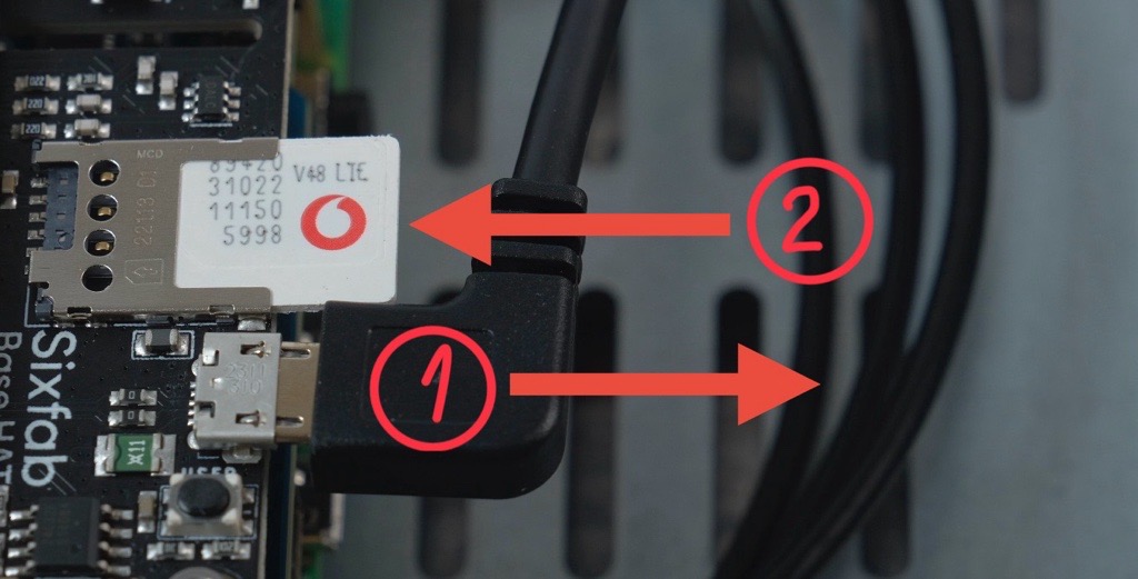
- Reconnect the micro-USB cable to the same connector it was disconnected from in step 4.
Do not skip this step. If the micro-USB cable stays disconnected, the LTE option will not appear in the management interface and the modem will not work.
- Verify Functionality:
There are two options to verify the SIM card functionality:
- If you use your Scout in Sensor Mode, connect the Scout to your local network and check its LTE status on the network management page.
- If you use your Scout in Cloud Mode, you can view the LTE status in the Dronetag App.
⚙️ LTE Configuration & Setup
Further configuration of LTE connectivity and APN (if needed) is covered in our Networking Guide:
📘 SIM Card Installation and LTE Setup
✅ Verify LTE Functionality
To confirm whether the Scout has connected to the mobile network, follow the instructions in the networking section:
🔍 Verify Functionality and LTE
- Reassemble the Device:
After confirming the device is functioning correctly, reattach the cover, carefully flip the device over, and tighten the 12 bolts (refer back to Step 2).
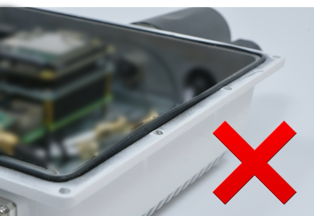
Pay special attention to assembling the device properly to prevent water ingress and avoid damaging the device.
Take extra care about the correct position of the sealing.

Custom SIM Card Requirements
Dronetag Scout supports custom LTE SIM cards for independent connectivity. While the hardware is globally compatible, successful operation depends on your carrier’s plan and network policies.
Verified US Carriers
The following networks have been successfully tested and verified:
- AT&T
- T-Mobile
- Verizon
Critical Connectivity Restrictions
1. IMEI Whitelisting (Carrier Certification)
- Some carriers (especially for tablet or hotspot-specific plans) enforce an IMEI lock.
- Dronetag Scout utilizes a Quectel modem that is not certified under specific carrier-proprietary programs (such as Verizon Open Development or AT&T IoT Certification).
- If your plan is restricted to "certified devices only," the carrier will reject the connection based on the Scout's IMEI.
Solution: Use a "Bring Your Own Device" (BYOD) plan or a generic data/IoT plan that does not enforce hardware whitelisting.
2. FirstNet Incompatibility
- Dronetag Scout is not compatible with FirstNet SIM cards. The hardware does not support the specific bands or protocols required for this network.
3. Phone Plans vs. Data-Only Plans
- Avoid using SIM cards from standard smartphone plans. Carriers often detect the modem and block data or throttle it under hotspot/tethering limits.
Solution: Use dedicated data-only, mobile broadband, or IoT/M2M plans.
Network & Performance Tips
- LTE Only: Ensure your SIM supports 4G/LTE. SIM cards provisioned exclusively for 5G Standalone (SA) networks will not function in the Scout.
- Local vs. Roaming SIMs: Global/roaming SIMs (e.g., Hologram, Emnify) work but may introduce higher latency. For time-critical operations, a local carrier SIM is recommended.
- Coverage: Ensure your carrier provides LTE coverage in your area. Note that some carriers (like T-Mobile) use specific bands (e.g., B71) for rural coverage that may differ from standard phone reception.
Pre-Installation Checklist
- Disable PIN: Use a smartphone to ensure the SIM card has no PIN code lock enabled.
- Verify Data: Confirm the SIM has an active data balance in another device.
- APN Settings: Obtain the correct APN (Access Point Name) from your provider. You will need to enter this in the Dronetag App during configuration.
Quick Troubleshooting
If the Scout fails to connect despite a valid SIM:
- Contact your carrier to verify the plan isn't locked to a specific IMEI
- Request the carrier to switch your line to a "Generic/BYOD" data profile



Source pages
Every chapter of this document is a page of the Dronetag help site. Use these addresses to reach the latest version.
- 1What is in the Boxhelp.dronetag.cz/cs/dronetag-scout/installation-guide/what-is-in-box
- 2Installation Prerequisiteshelp.dronetag.cz/cs/dronetag-scout/installation-guide/installation-prerequisities
- 3Deployment Step-by-Step Guidehelp.dronetag.cz/cs/dronetag-scout/installation-guide/deployment
- 4Choosing Location for Scouthelp.dronetag.cz/cs/dronetag-scout/installation-guide/location
- 5Mounting the Scouthelp.dronetag.cz/cs/dronetag-scout/installation-guide/mounting-scout
- 6Mounting the Antennashelp.dronetag.cz/cs/dronetag-scout/installation-guide/mounting-antennas
- 7Inserting the SIM Cardhelp.dronetag.cz/cs/dronetag-scout/installation-guide/inserting-sim
- 8Examples of Installationhelp.dronetag.cz/cs/dronetag-scout/installation-guide/examples-installation